

We at Circuitdigest have worked on a lot of PCB projects, but have consistently faced a challenge during the assembly process. Specifically, when working with SMD components, the use of solder paste is crucial. While SMD stencils are the most efficient method for applying solder paste to a PCB, they can be difficult to obtain, particularly from local PCB manufacturers. As an alternative, manual application of solder paste can be a tedious task, especially when dealing with a high component count. Are you a hobbyist searching for an uncomplicated method to apply solder paste quickly and efficiently?
In this project, we are going to make such a device. We will be using bare minimum components such as a microcontroller, OLED display, motor driver, and the miniature geared dc motor along with some 3D printed parts. With a clear and straightforward UI, this device is made to be user-friendly. It is the best option for a variety of tasks since it can properly and quickly dispense solder paste. Thanks to its adjustable speed and dispensing rate, we can fine-tune the amount of solder paste getting dispensed.
How Does the Solder Paste Dispenser Work?
The working of the Solder Paste Dispenser is pretty simple. We will use a miniature DC motor with a gearbox to dispense the solder paste from the syringe. The motor is driven with an efficient motor driver chip, DRV8833. The heart of the dispenser will be an ATMEGA328P. An OLED display along with tactile buttons are included for easy configuration and operation.
Components Required to Build the Solder Paste Dispenser
All the parts you will require to build the Solder Paste Dispenser are listed below.
- Atmega328P-AU AVR Micro Controller – 1
- DRV8833 Motor Driver IC – 1
- OLED display 128x32 – 1
- N20 Geared DC motor with long screw shaft - 1
- SMD tactile switches - 5
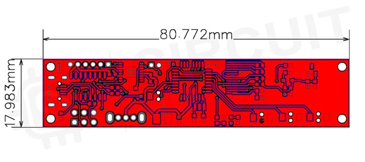
- Custom PCB – 1
- On /Off Switch – 1
- SMD resistors, capacitors, diodes, LEDs(All are 0603 package components)
- Other components
- Wires
- Connectors and pin headers
- 3D printed parts
- Other necessary tools
3D Printed Parts
The files for all the 3D printed parts can be downloaded from the GitHub link provided at the end of the article along with the Arduino sketch and bitmap file. It is recommended to print the parts with higher infill for better quality and sturdiness. Here you can download STL Files. Learn more about 3D printing by going through our getting started with 3D printing tutorial.
Solder Paste Dispenser Circuit Diagram
The complete circuit diagram for the Solder Paste Dispenser is shown below.

The circuit is straightforward and easy to understand. As mentioned earlier the controller we are using is an 8-bit AVR from a microchip, ATMEGA328P. You can also use an ATMEGA168 instead with some code optimizations.
A micro-USB port is used for both power and programming purposes. The VCC from the micro-USB port is fed to a slide switch. This switch is used to turn on and turn off the dispenser. A Power LED is provided to indicate the input power status. The data lines from the micro-USB are connected to the CH340C USB to UART converter. A 6 PIN standard ISP port is also provided as an alternative way to program the ATMEGA328 or to burn the bootloader if the MCU comes without one. If you are new, you can check out the tutorial on How to burn Arduino Bootloader to understand more.

The ATMEGA328 connections are pretty standard with the bare minimum, auxiliary components such as bypass capacitors and the reset circuit. A debug LED is connected to the pin PB5 (Arduino Pin D13). The display section consists of the 0.96” OLED module itself along with all the necessary components. A 3.3v regulator is included to power the OLED module. The switches are connected to the pins PB0, PB1, PB2 and PD4 (Arduino pins D8, D9, D10 and D4 respectively).
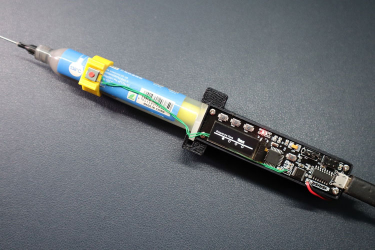
Since we are only using one phase of the motor driver, we only need two pins to control the DRV883. The AIN1 and AIN2 pins are connected to the PD5 and PD6 pins of the ATMEGA328. The motor is connected to the AOUT1 and AOUT2 pins of the DRV8833. Here is a fully assembled Solder Paste Dispenser.
Arduino Code for the Solder Paste Dispenser
As a first step make sure to install the U8g2 library from the library manager. The U8g2 library is used to control the OLED display. As always, we start the code by including all the necessary libraries. After that, we defined all the global variables, that we are going to use in the code. Along with that, we also created an instance for the U8g2 library to drive the OLED display.
#include <U8g2lib.h>  //U8g2 Library for the SSD1306 OLED
#include <Arduino.h>
#include <EEPROM.h>
//Define switch pins
#define SW4 4
#define SW3 10
#define SW2 9
#define SW1 8
//Define debug LED Pin
#define ledPin 13
//Define DRV8833 motor driver pins
#define AIN1 5
#define AIN2 6
//Define Global Variables
int Mode = 0;
int Dtime;
int Htime;
int screenrotation = 0;
unsigned long presstime = 0;
// U8g2 Instance for OLED
U8G2_SSD1306_128X32_UNIVISION_F_SW_I2C u8g2(U8G2_R2, /* clock=*/SCL, /* data=*/SDA, /* reset=*/U8X8_PIN_NONE);
In the Setup function, we have initialized all the required pins with their respective roles. Once it was done, we pulled the control pins of the DRV8833 to logic LOW to make sure the motor is turned off. Later we read the values of dispense and retraction times from EEPROM. This will ensure to load of the last saved values even after a power outage. Then we displayed the main screen on the OLED by calling the function menu, right after initializing the OLED class.
void setup() {
  //initialize pins
  pinMode(ledPin, OUTPUT);
  pinMode(SW1, INPUT_PULLUP);
  pinMode(SW2, INPUT_PULLUP);
  pinMode(SW3, INPUT_PULLUP);
  pinMode(SW4, INPUT_PULLUP);
  pinMode(AIN1, OUTPUT);
  pinMode(AIN2, OUTPUT);
  //set motor driver to off during startup
  digitalWrite(AIN1, LOW);
  digitalWrite(AIN2, LOW);
  //Get saved data from EEPROM
  Dtime = get_String(0, 1).toInt();
  Htime = get_String(5, 6).toInt();
  screenrotation = EEPROM.read(10);
  //initialize OLED and display the menu for first time
  u8g2.begin();
  u8g2.setFlipMode(screenrotation);
  u8g2.clearBuffer();
  menu(Mode);
  u8g2.sendBuffer();
}
The menu function is responsible for drawing the GUI elements to the OLED display. The function will check the current active mode and will draw the GUI for the respective mode.
void menu(int n) {
  //Draw main UI
  u8g2.drawLine(0, 21, 128, 21);
  u8g2.drawLine(0, 22, 128, 22);
  u8g2.drawLine(0, 23, 128, 23);
  switch (n) {
    case 0:
      u8g2.setFont(u8g2_font_baby_tf);
      u8g2.setCursor(5, 18);
      u8g2.print("Dispense Time");
      u8g2.drawDisc(32, 28, 3, U8G2_DRAW_ALL);
      u8g2.drawCircle(53, 28, 3, U8G2_DRAW_ALL);
      u8g2.drawCircle(75, 28, 3, U8G2_DRAW_ALL);
      u8g2.drawCircle(96, 28, 3, U8G2_DRAW_ALL);
      u8g2.setFont(u8g2_font_tenthinnerguys_tf);
      u8g2.setCursor(75, 18);
      u8g2.print(Dtime);
      u8g2.print("ms");
      break;
    case 1:
      u8g2.setFont(u8g2_font_baby_tf);
      u8g2.setCursor(23, 14);
      u8g2.print("Continuous Dispense");
      u8g2.drawCircle(32, 28, 3, U8G2_DRAW_ALL);
      u8g2.drawDisc(53, 28, 3, U8G2_DRAW_ALL);
      u8g2.drawCircle(75, 28, 3, U8G2_DRAW_ALL);
      u8g2.drawCircle(96, 28, 3, U8G2_DRAW_ALL);
      u8g2.drawBox(8, 8, 9, 9);
      u8g2.drawTriangle(110, 7, 110, 16, 118, 12);
      break;
    case 2:
      u8g2.setFont(u8g2_font_baby_tf);
      u8g2.setCursor(22, 14);
      u8g2.print("  Continuous Retract");
      u8g2.drawCircle(32, 28, 3, U8G2_DRAW_ALL);
      u8g2.drawCircle(53, 28, 3, U8G2_DRAW_ALL);
      u8g2.drawDisc(75, 28, 3, U8G2_DRAW_ALL);
      u8g2.drawCircle(96, 28, 3, U8G2_DRAW_ALL);
      u8g2.drawBox(8, 8, 9, 9);
      u8g2.drawTriangle(110, 7, 110, 16, 118, 12);
      break;
    case 3:
      u8g2.setFont(u8g2_font_baby_tf);
      u8g2.setCursor(5, 18);
      u8g2.print("Retract Time");
      u8g2.drawCircle(32, 28, 3, U8G2_DRAW_ALL);
      u8g2.drawCircle(53, 28, 3, U8G2_DRAW_ALL);
      u8g2.drawCircle(75, 28, 3, U8G2_DRAW_ALL);
      u8g2.drawDisc(96, 28, 3, U8G2_DRAW_ALL);
      u8g2.setFont(u8g2_font_tenthinnerguys_tf);
      u8g2.setCursor(75, 18);
      u8g2.print(Htime);
      u8g2.print("ms");
      break;
  }
}
The Motor function along with MotorD and MotorH functions is responsible for driving the N20 geared motor. These functions will manipulate the control pins of DRV8833 to control the direction and speed of the motor.
void Motor(int n) {
  //function to drive motor
  if (n == 0) {
    digitalWrite(AIN1, LOW);
    digitalWrite(AIN2, LOW);
  } else if (n == 1) {
    digitalWrite(AIN1, LOW);
    digitalWrite(AIN2, HIGH);
  } else if (n == 2) {
    digitalWrite(AIN1, HIGH);
    digitalWrite(AIN2, LOW);
  }
}
void MotorD() {
  Motor(1);
  delay(Dtime);
  Motor(0);
}
void MotorH() {
  Motor(2);
  delay(Htime);
  Motor(0);
}
The set_String and get_String functions are used to save and read the values to the EEPROM. These functions will use the EEPROM.write and EEPROM.read classes from EEPROM library for that purpose.
void set_String(int a, int b, String str) {
  EEPROM.write(a, str.length());
  for (int i = 0; i < str.length(); i++) {
    EEPROM.write(b + i, str[i]);
  }
}
String get_String(int a, int b) {
  String data = "";
  for (int i = 0; i < EEPROM.read(a); i++) {
    data += char(EEPROM.read(b + i));
  }
  return data;
}
The main loop function will monitor the status of all buttons. Once a key press is detected the MCU will run the corresponding function. You can use SW2 to change modes while SW1 and SW3 pins change the values. The switch connected to the BTN port is responsible for solder paste dispensing. When this switch is pressed the MCU will activate the Motor for the set time interval.
There are two variables we are using here; one is dispensing time and the other one is retracting time. The dispensing time indicates the time period to which the motor is driven in the forward direction to move the piston and dispense the solder paste. Once the solder paste is started to dispense, we need to run the motor in reverse to avoid any over dispense. This is controlled with the time variable retracting time. You can set and fine-tune these values from modes 1 and 4, with respect to the motor and dispensing nozzle you are using. Modes 2 and 3 can be used to move the piston forward or backwards continuously rather than in steps. This will be helpful when loading or removing a paste cartridge.
void loop() {
  //check if mode button (SW2) is pressed
  if (digitalRead(SW2) == LOW) {
    presstime = millis();
    delay(20);
    if (digitalRead(SW2) == LOW) {
      Mode++;
      if (Mode > 3) Mode = 0;
      digitalWrite(ledPin, HIGH);
      u8g2.clearBuffer();
      menu(Mode);
      if (Mode == 1 or Mode == 2) u8g2.drawRFrame(5, 5, 15, 15, 5);
      u8g2.sendBuffer();
      Motor(0);
      while (digitalRead(SW2) == LOW) {
        if (millis() - presstime > 3000) {  //Check if the mode button is pressed for 3S. If then flip screen to 180
          screenrotation = !screenrotation;
          EEPROM.write(10, screenrotation);
          u8g2.setFlipMode(screenrotation);
          u8g2.clearBuffer();
          menu(Mode);
          if (Mode == 1 or Mode == 2) u8g2.drawRFrame(5, 5, 15, 15, 5);
          u8g2.sendBuffer();
          Motor(0);
          delay(2000);
        }
      }
      digitalWrite(ledPin, LOW);
    }
  }
  //check if + and - buttons were pressed or not
  switch (Mode) {
    case 0:
      if (digitalRead(SW1) == LOW) {
        delay(20);
        if (digitalRead(SW1) == LOW) {
          Dtime -= 1;
          if (Dtime < 0) Dtime = 0;
          set_String(0, 1, String(Dtime));
          digitalWrite(ledPin, HIGH);
          u8g2.clearBuffer();
          menu(Mode);
          u8g2.sendBuffer();
          Serial.println(Dtime);
          Serial.println(Htime);
          while (digitalRead(SW1) == LOW);
          digitalWrite(ledPin, LOW);
        }
      }
      if (digitalRead(SW3) == LOW) {
        delay(20);
        if (digitalRead(SW3) == LOW) {
          Dtime += 1;
          if (Dtime > 3000) Dtime = 3000;
          set_String(0, 1, String(Dtime));
          digitalWrite(ledPin, HIGH);
          u8g2.clearBuffer();
          menu(Mode);
          u8g2.sendBuffer();
          Serial.println(Dtime);
          Serial.println(Htime);
          while (digitalRead(SW3) == LOW);
          digitalWrite(ledPin, LOW);
        }
      }
      break;
    case 1:
      if (digitalRead(SW1) == LOW) {
        delay(20);
        if (digitalRead(SW1) == LOW) {
          digitalWrite(ledPin, HIGH);
          u8g2.clearBuffer();
          menu(Mode);
          u8g2.drawRFrame(5, 5, 15, 15, 5);
          u8g2.sendBuffer();
          Motor(0);
          while (digitalRead(SW1) == LOW);
          digitalWrite(ledPin, LOW);
        }
      }
      if (digitalRead(SW3) == LOW) {
        delay(20);
        if (digitalRead(SW3) == LOW) {
          u8g2.clearBuffer();
          menu(Mode);
          u8g2.drawRFrame(106, 5, 15, 15, 5);
          u8g2.sendBuffer();
          Motor(1);
          while (digitalRead(SW3) == LOW);
          digitalWrite(ledPin, LOW);
        }
      }
      break;
    case 2:
      if (digitalRead(SW1) == LOW) {
        delay(20);
        if (digitalRead(SW1) == LOW) {
          digitalWrite(ledPin, HIGH);
          u8g2.clearBuffer();
          menu(Mode);
          u8g2.drawRFrame(5, 5, 15, 15, 5);
          u8g2.sendBuffer();
          Motor(0);
          while (digitalRead(SW1) == LOW);
          digitalWrite(ledPin, LOW);
        }
      }
      if (digitalRead(SW3) == LOW) {
        delay(20);
        if (digitalRead(SW3) == LOW) {
          u8g2.clearBuffer();
          menu(Mode);
          u8g2.drawRFrame(106, 5, 15, 15, 5);
          u8g2.sendBuffer();
          Motor(2);
          while (digitalRead(SW3) == LOW);
          digitalWrite(ledPin, LOW);
        }
      }
      break;
    case 3:
      if (digitalRead(SW1) == LOW) {
        delay(20);
        if (digitalRead(SW1) == LOW) {
          Htime -= 1;
          if (Htime < 0) Htime = 0;
          set_String(5, 6, String(Htime));
          digitalWrite(ledPin, HIGH);
          u8g2.clearBuffer();
          menu(Mode);
          u8g2.sendBuffer();
          Serial.println(Dtime);
          Serial.println(Htime);
          while (digitalRead(SW1) == LOW);
          digitalWrite(ledPin, LOW);
        }
      }
      if (digitalRead(SW3) == LOW) {
        delay(20);
        if (digitalRead(SW3) == LOW) {
          Htime += 1;
          if (Htime > 1000) Htime = 1000;
          set_String(5, 6, String(Htime));
          digitalWrite(ledPin, HIGH);
          u8g2.clearBuffer();
          menu(Mode);
          u8g2.sendBuffer();
          Serial.println(Dtime);
          Serial.println(Htime);
          while (digitalRead(SW3) == LOW);
          digitalWrite(ledPin, LOW);
        }
      }
      break;
  }
  //Check if dispense button is pressed or not.If pressed start dispensing as per the set speed
  if (digitalRead(SW4) == LOW) {
    delay(20);
    if (digitalRead(SW4) == LOW) {
      digitalWrite(ledPin, HIGH);
      MotorD();
      MotorH();
      while (digitalRead(SW4) == LOW);
      digitalWrite(ledPin, LOW);
    }
  }
}
You can download all the necessary files from the Circuit Digest GitHub repo, from the following link


Complete Project Code
#include <U8g2lib.h>  //U8g2 Library for the SSD1306 OLED
#include <Arduino.h>
#include <EEPROM.h>
//Define switch pins
#define SW4 4
#define SW3 10
#define SW2 9
#define SW1 8
//Define debug LED Pin
#define ledPin 13
//Define DRV8833 motor driver pins
#define AIN1 5
#define AIN2 6
//Define Global Variables
int Mode = 0;
int Dtime;
int Htime;
int screenrotation = 0;
unsigned long presstime = 0;
// U8g2 Instance for OLED
U8G2_SSD1306_128X32_UNIVISION_F_SW_I2C u8g2(U8G2_R2, /* clock=*/SCL, /* data=*/SDA, /* reset=*/U8X8_PIN_NONE);
void setup() {
  //initialize pins
  pinMode(ledPin, OUTPUT);
  pinMode(SW1, INPUT_PULLUP);
  pinMode(SW2, INPUT_PULLUP);
  pinMode(SW3, INPUT_PULLUP);
  pinMode(SW4, INPUT_PULLUP);
  pinMode(AIN1, OUTPUT);
  pinMode(AIN2, OUTPUT);
  //set motor driver to off during startup
  digitalWrite(AIN1, LOW);
  digitalWrite(AIN2, LOW);
  //Get saved data from EEPROM
  Dtime = get_String(0, 1).toInt();
  Htime = get_String(5, 6).toInt();
  screenrotation = EEPROM.read(10);
  //initialize OLED and display the menu for first time
  u8g2.begin();
  u8g2.setFlipMode(screenrotation);
  u8g2.clearBuffer();
  menu(Mode);
  u8g2.sendBuffer();
}


void menu(int n) {
  //Draw main UI
  u8g2.drawLine(0, 21, 128, 21);
  u8g2.drawLine(0, 22, 128, 22);
  u8g2.drawLine(0, 23, 128, 23);
  switch (n) {
    case 0:
      u8g2.setFont(u8g2_font_baby_tf);
      u8g2.setCursor(5, 18);
      u8g2.print("Dispense Time");
      u8g2.drawDisc(32, 28, 3, U8G2_DRAW_ALL);
      u8g2.drawCircle(53, 28, 3, U8G2_DRAW_ALL);
      u8g2.drawCircle(75, 28, 3, U8G2_DRAW_ALL);
      u8g2.drawCircle(96, 28, 3, U8G2_DRAW_ALL);
      u8g2.setFont(u8g2_font_tenthinnerguys_tf);
      u8g2.setCursor(75, 18);
      u8g2.print(Dtime);
      u8g2.print("ms");
      break;
    case 1:
      u8g2.setFont(u8g2_font_baby_tf);
      u8g2.setCursor(23, 14);
      u8g2.print("Continuous Dispense");
      u8g2.drawCircle(32, 28, 3, U8G2_DRAW_ALL);
      u8g2.drawDisc(53, 28, 3, U8G2_DRAW_ALL);
      u8g2.drawCircle(75, 28, 3, U8G2_DRAW_ALL);
      u8g2.drawCircle(96, 28, 3, U8G2_DRAW_ALL);
      u8g2.drawBox(8, 8, 9, 9);
      u8g2.drawTriangle(110, 7, 110, 16, 118, 12);
      break;
    case 2:
      u8g2.setFont(u8g2_font_baby_tf);
      u8g2.setCursor(22, 14);
      u8g2.print("  Continuous Retract");
      u8g2.drawCircle(32, 28, 3, U8G2_DRAW_ALL);
      u8g2.drawCircle(53, 28, 3, U8G2_DRAW_ALL);
      u8g2.drawDisc(75, 28, 3, U8G2_DRAW_ALL);
      u8g2.drawCircle(96, 28, 3, U8G2_DRAW_ALL);
      u8g2.drawBox(8, 8, 9, 9);
      u8g2.drawTriangle(110, 7, 110, 16, 118, 12);
      break;
    case 3:
      u8g2.setFont(u8g2_font_baby_tf);
      u8g2.setCursor(5, 18);
      u8g2.print("Retract Time");
      u8g2.drawCircle(32, 28, 3, U8G2_DRAW_ALL);
      u8g2.drawCircle(53, 28, 3, U8G2_DRAW_ALL);
      u8g2.drawCircle(75, 28, 3, U8G2_DRAW_ALL);
      u8g2.drawDisc(96, 28, 3, U8G2_DRAW_ALL);
      u8g2.setFont(u8g2_font_tenthinnerguys_tf);
      u8g2.setCursor(75, 18);
      u8g2.print(Htime);
      u8g2.print("ms");
      break;
  }
}


void Motor(int n) {
  //function to drive motor
  if (n == 0) {
    digitalWrite(AIN1, LOW);
    digitalWrite(AIN2, LOW);
  } else if (n == 1) {
    digitalWrite(AIN1, LOW);
    digitalWrite(AIN2, HIGH);
  } else if (n == 2) {
    digitalWrite(AIN1, HIGH);
    digitalWrite(AIN2, LOW);
  }
}

void MotorD() {
  Motor(1);
  delay(Dtime);
  Motor(0);
}
void MotorH() {
  Motor(2);
  delay(Htime);
  Motor(0);
}

void set_String(int a, int b, String str) {
  EEPROM.write(a, str.length());
  for (int i = 0; i < str.length(); i++) {
    EEPROM.write(b + i, str[i]);
  }
}

String get_String(int a, int b) {
  String data = "";
  for (int i = 0; i < EEPROM.read(a); i++) {
    data += char(EEPROM.read(b + i));
  }
  return data;
}

void loop() {

  //check if mode button (SW2) is pressed
  if (digitalRead(SW2) == LOW) {
    presstime = millis();
    delay(20);
    if (digitalRead(SW2) == LOW) {
      Mode++;
      if (Mode > 3) Mode = 0;
      digitalWrite(ledPin, HIGH);
      u8g2.clearBuffer();
      menu(Mode);
      if (Mode == 1 or Mode == 2) u8g2.drawRFrame(5, 5, 15, 15, 5);
      u8g2.sendBuffer();
      Motor(0);
      while (digitalRead(SW2) == LOW) {
        if (millis() - presstime > 3000) {  //Check if the mode button is pressed for 3S. If then flip screen to 180
          screenrotation = !screenrotation;
          EEPROM.write(10, screenrotation);
          u8g2.setFlipMode(screenrotation);
          u8g2.clearBuffer();
          menu(Mode);
          if (Mode == 1 or Mode == 2) u8g2.drawRFrame(5, 5, 15, 15, 5);
          u8g2.sendBuffer();
          Motor(0);
          delay(2000);
        }
      }
      digitalWrite(ledPin, LOW);
    }
  }

  //check if + and - buttons were pressed or not
  switch (Mode) {
    case 0:
      if (digitalRead(SW1) == LOW) {
        delay(20);
        if (digitalRead(SW1) == LOW) {
          Dtime -= 1;
          if (Dtime < 0) Dtime = 0;
          set_String(0, 1, String(Dtime));
          digitalWrite(ledPin, HIGH);
          u8g2.clearBuffer();
          menu(Mode);
          u8g2.sendBuffer();
          Serial.println(Dtime);
          Serial.println(Htime);
          while (digitalRead(SW1) == LOW)
            ;
          digitalWrite(ledPin, LOW);
        }
      }
      if (digitalRead(SW3) == LOW) {
        delay(20);
        if (digitalRead(SW3) == LOW) {
          Dtime += 1;
          if (Dtime > 3000) Dtime = 3000;
          set_String(0, 1, String(Dtime));
          digitalWrite(ledPin, HIGH);
          u8g2.clearBuffer();
          menu(Mode);
          u8g2.sendBuffer();
          Serial.println(Dtime);
          Serial.println(Htime);
          while (digitalRead(SW3) == LOW)
            ;
          digitalWrite(ledPin, LOW);
        }
      }
      break;
    case 1:
      if (digitalRead(SW1) == LOW) {
        delay(20);
        if (digitalRead(SW1) == LOW) {

          digitalWrite(ledPin, HIGH);
          u8g2.clearBuffer();
          menu(Mode);
          u8g2.drawRFrame(5, 5, 15, 15, 5);
          u8g2.sendBuffer();
          Motor(0);
          while (digitalRead(SW1) == LOW)
            ;
          digitalWrite(ledPin, LOW);
        }
      }
      if (digitalRead(SW3) == LOW) {
        delay(20);
        if (digitalRead(SW3) == LOW) {
          u8g2.clearBuffer();
          menu(Mode);
          u8g2.drawRFrame(106, 5, 15, 15, 5);
          u8g2.sendBuffer();
          Motor(1);
          while (digitalRead(SW3) == LOW)
            ;
          digitalWrite(ledPin, LOW);
        }
      }
      break;
    case 2:
      if (digitalRead(SW1) == LOW) {
        delay(20);
        if (digitalRead(SW1) == LOW) {

          digitalWrite(ledPin, HIGH);
          u8g2.clearBuffer();
          menu(Mode);
          u8g2.drawRFrame(5, 5, 15, 15, 5);
          u8g2.sendBuffer();
          Motor(0);
          while (digitalRead(SW1) == LOW)
            ;
          digitalWrite(ledPin, LOW);
        }
      }
      if (digitalRead(SW3) == LOW) {
        delay(20);
        if (digitalRead(SW3) == LOW) {
          u8g2.clearBuffer();
          menu(Mode);
          u8g2.drawRFrame(106, 5, 15, 15, 5);
          u8g2.sendBuffer();
          Motor(2);
          while (digitalRead(SW3) == LOW)
            ;
          digitalWrite(ledPin, LOW);
        }
      }
      break;
    case 3:
      if (digitalRead(SW1) == LOW) {
        delay(20);
        if (digitalRead(SW1) == LOW) {
          Htime -= 1;
          if (Htime < 0) Htime = 0;
          set_String(5, 6, String(Htime));
          digitalWrite(ledPin, HIGH);
          u8g2.clearBuffer();
          menu(Mode);
          u8g2.sendBuffer();
          Serial.println(Dtime);
          Serial.println(Htime);
          while (digitalRead(SW1) == LOW)
            ;
          digitalWrite(ledPin, LOW);
        }
      }
      if (digitalRead(SW3) == LOW) {
        delay(20);
        if (digitalRead(SW3) == LOW) {
          Htime += 1;
          if (Htime > 1000) Htime = 1000;
          set_String(5, 6, String(Htime));
          digitalWrite(ledPin, HIGH);
          u8g2.clearBuffer();
          menu(Mode);
          u8g2.sendBuffer();
          Serial.println(Dtime);
          Serial.println(Htime);
          while (digitalRead(SW3) == LOW)
            ;
          digitalWrite(ledPin, LOW);
        }
      }
      break;
  }

  //Check if dispense button is pressed or not.If pressed start dispensing as per the set speed
  if (digitalRead(SW4) == LOW) {
    delay(20);
    if (digitalRead(SW4) == LOW) {
      digitalWrite(ledPin, HIGH);
      MotorD();
      MotorH();
      while (digitalRead(SW4) == LOW)
        ;
      digitalWrite(ledPin, LOW);
    }
  }
}Comments
The gerber file has been uploaded to the Github repo. Please check now.
hi
I'd like too to get the Gerber file, I've tried using the photo on this page but it doesn't work fine
Regards
The gerber file has been uploaded to the Github repo.
The gerber file has been uploaded to the Github repo.
Hello! Do you still have the PCB files? I really need them.

Nice. I think I would like to make one of these but the most important information is missing from the article, The PCB gerbers! Is there any chance of those or is a PCB available?