
Ever wondered how our world is moving towards immersive reality? We are continuously finding new ways and methods to interact with our surroundings using virtual reality, mixed reality, augmented reality, and air gesture mouse technologies. New devices are coming out every day with these fast-paced technologies to impress us with their new interactive technologies.
These immersive technologies are used in gaming, interactive activities, entertainment, and many other applications. In this tutorial, we'll explore how to build a DIY air mouse using an accelerometer and Arduino that gives you a revolutionary way to interact with your system instead of using a traditional mouse. Our gaming geeks must know that a few years back, Nintendo, a gaming company, sold an idea of a 3D interactive method to interact with their consoles with the help of a handheld controller known as the Wii controller. This wireless mouse circuit uses an accelerometer to locate your gestures and send signals to the system wirelessly. If you want to know more about this technology, you can check out their patent EP1854518B1, this will give you a complete idea of how this technology works.

Inspired by this idea we are going to make an "Air mouse", to interact with systems just by moving the console in the air, but instead of using 3-dimensional coordinate references, we are only going to use 2-dimensional coordinate references so we can imitate the actions of the computer mouse since the mouse works in two dimensions X and Y.
The concept behind this Wireless 3D Air Mouse is very simple. We will use an accelerometer to get the value of the acceleration of the actions and motions of the “Air mouse” along the x-axis and y-axis. Based on these accelerometer readings, our gesture controlled Arduino based air mouse will control the cursor position and execute mouse actions through Python software drivers running on your computer.
Table of Contents
- Wireless Mouse Circuit Diagram and Components Required
- Wireless Mouse Circuit Diagram
- Air Gesture Mouse Circuit Setup and Connections
- How Air Gesture Mouse Works - Process Flow
- DIY Air Mouse Benefits and Applications
- Programming the Arduino for Air Mouse
- Python Driver Script for Wireless Mouse Control
- Testing the Arduino Air Mouse
- Future Enhancement
- Frequently Asked Questions
- Gesture Controlled Arduino Based Air Mouse GitHub Repository
- Advanced Gesture-Controlled Projects and Applications
Wireless Mouse Circuit Diagram and Components Required
- Arduino Nano (any model) - Learn more about Arduino Nano projects
- Accelerometer ADXL335 Module - Explore accelerometer tutorials
- Bluetooth HC-05 Module - Browse Bluetooth projects
- Push buttons - Understanding button debouncing
- Python Installed computer - Arduino-Python integration guide
To learn more about installing Python on a computer, follow the previous tutorial on Arduino-Python LED Controlling.
Wireless Mouse Circuit Diagram

Air Gesture Mouse Circuit Setup and Connections
To control your computer with the movements of your hand you need an accelerometer that gives out the acceleration along the X and Y-axis and to make the whole system wireless a Bluetooth module is used to transfer the signal wirelessly to your system.
Here, an ADXL335 accelerometer is used, it's a MEMS-based triple-axis module outputting the acceleration along the X, Y, and Z-axis but as told previously, for controlling the mouse, we would only need the acceleration along the X and Y-axis. Learn more about using the ADXL335 accelerometer with Arduino in our previous projects:
- Arduino Based Vehicle Accident Alert System Using GPS, GSM, and Accelerometer
- Ping Pong Game using Arduino and Accelerometer
- Accelerometer-Based Hand Gesture Controlled Robot Using Arduino
- Earthquake Detector Alarm using Arduino
Here the Xout and Yout pins of the accelerometer are connected to the Analog, A0, and A1 pins of Arduino, and for transmitting the signals from the Arduino to the system Bluetooth module HC-05 is used here, since the Bluetooth works over the Tx and Rx pin connections, so we use software serial pins D2 and D3. It is connected using Software Serial because if we connect the Bluetooth with the hardware serial and start getting the readings over the Python console, it would show errors for the mismatched baud rate, as the Bluetooth would be communicating with the Python on its own baud rate. Learn more about using Bluetooth modules by going through various Bluetooth-based projects using different microcontrollers, including Arduino.
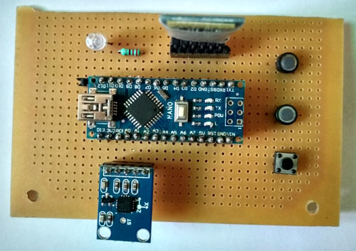
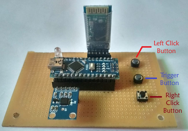
Our DIY air mouse using an accelerometer Arduino incorporates three push buttons: one trigger button to activate the air mouse mode, and two additional buttons for left and right mouse clicks, as demonstrated in the hardware setup below:
How Air Gesture Mouse Works - Process Flow
The flow chart shows the process flow of Arduino-based Air Mouse:
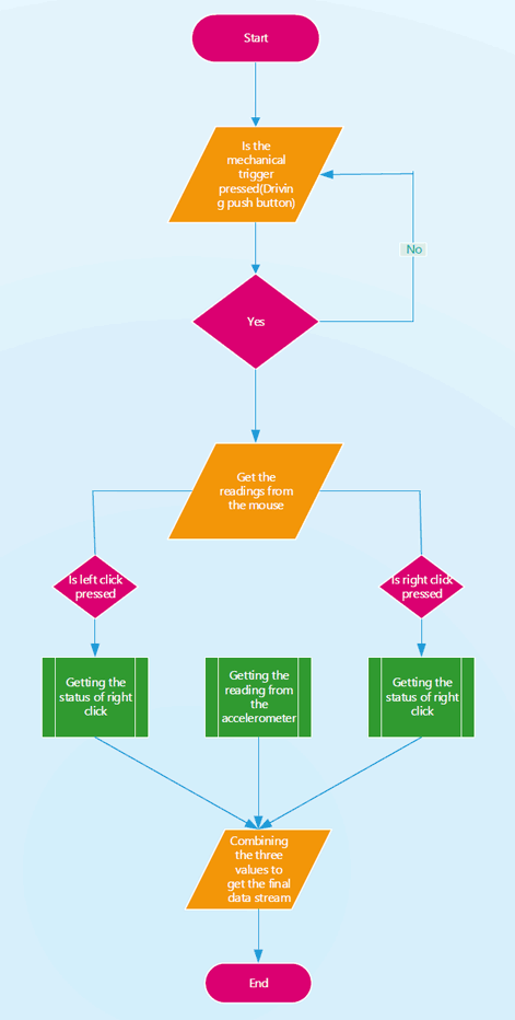
1. The system continuously checks for the mechanical trigger to be pressed until it is pressed, and we can work normally with the computer's mouse.
2. When the system detects a button press, the control for the mouse is transferred to the Air Mouse.
3. As the trigger button is pressed the system starts to transfer the readings of the mouse to the computer. The system reading consists of the accelerometer readings, and the readings for the left and right click.
4. The system readings consist of the data stream of 1 byte or 8 bits, in which the first three bits consist of the X-coordinates, the second three bits consist of the Y-coordinates, the second last bit is the status bit for getting the status of the left click of the mouse and the last bit is the status bit for getting the status of the right click.
5. The value of the first three bits, i.e., X-coordinate, can range from 100<=Xcord<=999, whereas the value for the Y-coordinate can range from 100<=Ycord<=800. The values for the right click and left click are the binary values either 0 or 1 in which 1 indicates the click is made and 0 that click is not made by the user.
6. To not let the bouncing of the button affect the position of the cursor a known delay of 4 seconds is kept after every click of the trigger button of the mouse.
7. For the right and left click in the air mouse, we have to first press either left or right pushbutton, and after that, we have to press the trigger button to move to the position of the air mouse where we want.
DIY Air Mouse Benefits and Applications
Aspect | Details |
|---|---|
Key Benefits |
|
Technology Used | Gesture-controlled input using an accelerometer and Arduino |
Presentation Use | Allows remote slide control for presenters without needing to be near the computer |
Gaming Applications | Provides intuitive gesture-based controls for immersive gaming experiences |
Accessibility Use | Helps users with disabilities interact with computer systems through hand gestures |
Customization | Modular wireless mouse circuit design allows for easy upgrades and adaptations based on specific user requirements. |
Programming the Arduino for Air Mouse
The Arduino should be programmed to read the acceleration values in the X and Y-axis. The complete program is given at the end, below are the important snippets from the code.
Setting up the global variables
As previously said we will hook up the Bluetooth module with the software serial pins. So to set the software serial we need to declare the library of software serial and set up the pins for Tx and Rx. In Arduino Nano and Uno Pin 2 and 3 can work as a software serial. Next, we declare the Bluetooth object from the software serial library to set up the pin for the Tx and Rx.
#include <SoftwareSerial.h>
const int rxpin = 2, txpin = 3;
SoftwareSerial bluetooth(rxpin, txpin);
const int x=A0;
const int y=A1;
int xh, yh;
int xcord, ycord;
const int trigger = 5;
int lstate = 0;
int rstate = 0;
const int lclick = 6;
const int rclick = 7;
const int led = 8;
Void setup()
In the setup function, we are going to set the variables to tell the program whether they will act as input or output. The trigger button would be set up as an input pull-up, and the left and right clicks would be declared as input and set up as High to make them act as input pull-ups.
Also, set the baud rate for the serial and Bluetooth communication to 9600.
  void setup()
{
  pinMode(x,INPUT);
  pinMode(y,INPUT);
  pinMode(trigger,INPUT_PULLUP)
  pinMode(lclick,INPUT);
  pinMode(rclick,INPUT);
  pinMode(led, OUTPUT);
  digitalWrite(lclick,HIGH);
  digitalWrite(rclick,HIGH);
  Serial.begin(9600);
  bluetooth.begin(9600);
}
Void loop()
As we would need a trigger button to tell when we need to send the system the data stream, so we set up the whole code inside the while loop which will continuously monitor the digital state of the pull-up trigger, as it goes low it will pass it further for the processing.
As we have attached an LED to let us know the status of the system for when the trigger button is pressed, we initially set the LED to low outside the while loop as its default condition and high inside the while loop, which will light up the LED whenever the trigger button is pressed.
To read the status of the left and right click button we have globally declared two variables lclick and rclick whose values initially were set up to 0.
In the loop, set the value of those variables according to the digital status of the left and right-click buttons to check whether the buttons are pressed or not.
We would be reading the values of the X and Y out pins of the accelerometer using the analogRead function and would map those values to the screen size to get the mouse pointer moving across the whole screen. Since the screen size is the pixels in the screen, we need to set it up accordingly and as we need the output value to be three digits we have deliberately set up the range for the X as 100<=X<=999, and similarly the value for the Y as 100<=Y<=800. Remember, the pixels are being read from the top left corner i.e. the top left corner has the value (0,0), but since we have declared three digits for the x and y our values would be read from the point (100,100).
Further, print the value of the coordinates and the status of the click over the serial and Bluetooth with the help of Serial. print and Bluetooth. Print functions help in getting the values on the serial monitor and over your system via Bluetooth.
At last, due to the bouncing of a button, a single value may be repeated, which would cause a mouse cursor to linger over a single position, so to get rid of this, we have to add this delay.
void loop()
{
digitalWrite(led,LOW);
  while(digitalRead(trigger)==LOW)
  {
    digitalWrite(led, HIGH);
    lstate = digitalRead(lclick);
    rstate = digitalRead(rclick);
    xh=analogRead(x);
    yh=analogRead(y);
    xcord=map(xh,286,429,100,999);
    ycord=map(yh,282,427,100,800);
    Serial.print(xcord);
    Serial.print(ycord);
    if (lstate == LOW)
    Serial.print(1);
    else
    Serial.print(0);
    if (rstate == LOW)
    Serial.print(1);
    else
    Serial.print(0);
    bluetooth.print(xcord);
    bluetooth.print(ycord);
    if (lstate == LOW)
    bluetooth.print(1);
    else
    bluetooth.print(0);
    if (rstate == LOW)
    bluetooth.print(1);
    else
    bluetooth.print(0);
    delay(4000);
   } }
Python Driver Script for Wireless Mouse Control
As of now, we have completed the hardware and its firmware part. Now, to get the air mouse working, we need to have a driver script that can decode the signals from the air mouse into the cursor movements, so for this, we have chosen Python. Python is a scripting language, and by scripting here we mean that it helps us to get control of other programs, as here we are controlling the mouse cursor.
So, open your Python shell and get the following libraries installed using the below commands:
pip install serial
pip install pyautogui
The serial library enables robust communication with our wireless mouse circuit through COM ports, facilitating data reception and processing from the Bluetooth module. The pyautogui library provides comprehensive GUI automation capabilities, specifically cursor control and click operations essential for air gesture mouse functionality.
Driver Implementation: Now let's get to the code for the drivers, the first thing we need to do is import the serial and pyautogui libraries, and then from the serial library, we have to set the com port for the communication with a baud rate of 9600, the same as Bluetooth.serial is operating at. For this, you have to connect the Bluetooth module to your system, and then in the system settings, you have to check out which COM port it is connected to.
Continuous Data Processing: The next thing is to read the serial communication from the Bluetooth to the system and to keep it going continuously, keep the rest of the code in a continuous loop with the help of while 1.
Data Parsing Protocol: As said previously, Arduino is sending out 8 bits, the first 6 for the coordinates and the last two for the status of the click buttons. So read all the bits with the help of the ser. read and set up its length to 8 bits.
Coordinate Processing: Next, divide the bits for the cursor coordinates and clicks by slicing them over, and then further slice down the cursor bits into X and Y coordinates separately. The same goes for the left and right clicks. Now, from the communication, we are getting a byte string, and we need to convert it into an integer so that it can fit in the coordinates. We do this by decoding them and then typecasting them into integers.
Cursor Control: Now, to move the cursor, we use the pyautogui moveTo function, which takes as arguments those integer coordinates and moves the cursor to that position.
Next check for the clicks, we do this by using the last two bits and pyautogui's click function, its default click is the left one, however, we can set it to right by declaring the button value to right, we can also define the number of clicks to set it off to a double click by setting up the clicks parameter to 2.
Below is the complete Python code to be run on the computer:
import serial
import pyautogui
ser=serial.Serial('com3',9600)
while 1:
    k=ser.read(8)
    cursor=k[:6]
    click=k[6:]
    x=cursor[:3]
    y=cursor[3:]
    l=click[0]
    r=click[1]
    xcor=int(x.decode('utf-8'))
    ycor=int(y.decode('utf-8'))
    pyautogui.moveTo(xcor,ycor)
    if l==49:
        pyautogui.click(clicks=2)
    elif r==49:
        pyautogui.click(button='right', clicks=2)
Testing the Arduino Air Mouse
So to operate the Air Mouse, attach a power source to it. It can be from the Arduino Nano USB slot or from the 5V regulated power supply using a 7805 IC. Then run the Python driver script by setting the COM port that your Bluetooth is connected to. As the script runs, you would see a time lag in the blinking of the Bluetooth, which means it's connected to your system. Confirming wireless communication establishment between your DIY air mouse using an accelerometer, Arduino, and the computer. Then, to operate it, click the trigger button, and you will see the position of the coordinates change. If you want the left or right click, then first press the left or right pushbutton and the trigger button together, you will see the action of the click at a changed location of the cursor.
There is a Bluetooth connection. The Bluetooth would blink with a time lag as the script ran, indicating that it was connected to your system. Then, to operate it, click the trigger button. The coordinates' position will change, and if you want to click left or right, press the trigger button and the left or right pushbutton simultaneously. This will cause the cursor to move to a new location.
Future Enhancement
» Integration of Other Sensors: To enable accurate 3D gesture detection, combine gyroscope sensors with the accelerometer.
» Better Gesture Recognition: Employ cutting-edge algorithms to identify increasingly intricate and precise gesture patterns.
» Machine Learning Integration: Put ML models into practice to allow for customized gesture recognition and gradually adjust to the habits of each user.
» Improved Wireless Communication: For quicker and more dependable data transfer, switch to more robust wireless protocols like Wi-Fi or Bluetooth Low Energy (BLE).
» Haptic Feedback: To provide real-time physical reactions to user inputs, incorporate tactile feedback systems or vibration motors.
» Battery Optimization: Optimize the battery's power management for extended use, perhaps through effective energy harvesting or sleep modes.
» Ergonomic Design Enhancements: Create a wearable, more comfortable form factor for extended use.
» Cross-Platform Compatibility: Verify that the gadget functions flawlessly on a variety of operating systems, including Android, Linux, macOS, and Windows.
Frequently Asked Questions
⇥ Can I use an Arduino Air Mouse with an MPU6050 accelerometer instead of an ADXL335?
The MPU6050 does function, but it needs I2C communication rather than analog pins. Attach the Arduino Nano's SDA to A4 and SCL to A5. Install the MPU6050 library, then change the code to use I2C data reading rather than analogRead().
⇥ Why does the cursor on my Arduino Air Mouse move erratically or not at all?
Inaccurate map() function calibration values are typically the source of jerky movement. Adapt the accelerometer range values (286,429 for X-axis, 282,427 for Y-axis) to the output of your module. For a smoother response, lower the 4-second delay to 1000ms and verify the stability of the 5V power supply.
⇥ Which version of Python works with the Arduino?
The code provided works best with Python 3.6+. Use print statements without parentheses and adjust the decoding procedure for Python 2.7. Install the necessary libraries: Install pyserial and pyautogui with pip. Verify that the COM port is configured correctly in Device Manager for Windows.
⇥ Is the Arduino Air Mouse compatible with Linux, Mac, or just Windows?
It is cross-platform compatible, yes. PyAutoGUI works directly with Windows. Pyautogui installation on Macs requires pip3 installation. For GUI control, Linux may require sudo apt-get install python3-tk python3-dev. Modify the format of the COM port: Mac/Linux uses '/dev/ttyUSB0' or '/dev/ttyACM0', while Windows uses 'com3'.
Gesture Controlled Arduino Based Air Mouse GitHub Repository
Through our extensive GitHub repository, you can obtain the full source code and comprehensive documentation of the DIY air mouse using an accelerometer Arduino project. To assist you in building your air gesture mouse system, the repository contains the complete Arduino firmware, Python driver script, comprehensive wireless mouse circuit diagram, component specifications, and troubleshooting instructions.


Advanced Gesture-Controlled Projects and Applications
Expand your knowledge of gesture-controlled systems with these innovative projects that demonstrate various applications of accelerometer-based control systems. Previously, we have used this Gesture-Controlled to build many interesting projects. If you want to know more about those topics, links are given below.

Arduino gesture-controlled Robot using Accelerometer
For the demo purpose, we have shown a use case of the Pantomime in a chassis of a 4WD, which here can be easily altered with a smart wheelchair. The Pantomime responds to the hand gestures to control the 4WD rover. The motions we were able to show using the prototype are forward, backward, left, and right.

Gesture-based Intelligent Appliance Control Robot
This system detects the hand and identifies the gesture with the help of artificial intelligence, and based on that, it controls the appliances. It can be programmed to recognize different gestures and control the appliances accordingly

In this tutorial, we are going to use the MediaPipe Python library to detect our hand gestures and control the Raspberry Pi media player using that. Here we will use a total of six Hand Gestures, i.e., Open & closed fists, and up, down, left, and Right movements of the hand. Open and closed fist gestures are used to play and pause the video.
Check the detailed working Video below.
Complete Project Code
Python Script:
import serial
import pyautogui
ser=serial.Serial('com3',9600)
while 1:
    k=ser.read(8)
    cursor=k[:6]
    click=k[6:]
    x=cursor[:3]
    y=cursor[3:]
    l=click[0]
    r=click[1]
    xcor=int(x.decode('utf-8'))
    ycor=int(y.decode('utf-8'))
    pyautogui.moveTo(xcor,ycor)
    if l==49:
        pyautogui.click(clicks=2)
    elif r==49:
        pyautogui.click(button='right', clicks=2)

Arduino Code:
#include <SoftwareSerial.h>
const int rxpin = 2, txpin = 3;
SoftwareSerial bluetooth(rxpin, txpin);
const int x=A0;
const int y=A1;
int xh, yh;
int xcord, ycord;
const int trigger = 5;
int lstate = 0;
int rstate = 0;
const int lclick = 6;
const int rclick = 7;
const int led = 8;
void setup()
{
  pinMode(x,INPUT);
  pinMode(y,INPUT);
  pinMode(trigger,INPUT_PULLUP);
  pinMode(lclick,INPUT);
  pinMode(rclick,INPUT);
  pinMode(led, OUTPUT);
  digitalWrite(lclick,HIGH);
  digitalWrite(rclick,HIGH);
  Serial.begin(9600);
  bluetooth.begin(9600);
}
void loop()
{
digitalWrite(led,LOW);
  while(digitalRead(trigger)==LOW)
  {
    digitalWrite(led, HIGH);
    lstate = digitalRead(lclick);
    rstate = digitalRead(rclick);
    xh=analogRead(x);
    yh=analogRead(y);
    xcord=map(xh,286,429,100,999);
    ycord=map(yh,282,427,100,800);
    Serial.print(xcord);
    Serial.print(ycord);
    if (lstate == LOW)
    Serial.print(1);
    else
    Serial.print(0);
    if (rstate == LOW)
    Serial.print(1);
    else
    Serial.print(0);
    bluetooth.print(xcord);
    bluetooth.print(ycord);
    if (lstate == LOW)
    bluetooth.print(1);
    else
    bluetooth.print(0);
    if (rstate == LOW)
    bluetooth.print(1);
    else
    bluetooth.print(0);
    delay(4000);
   }
}
Python driver script
import serial
import pyautogui
ser=serial.Serial('com3',9600)
while 1:
    k=ser.read(8)
    cursor=k[:6]
    click=k[6:]
    x=cursor[:3]
    y=cursor[3:]
    l=click[0]
    r=click[1]
    xcor=int(x.decode('utf-8'))
    ycor=int(y.decode('utf-8'))
    pyautogui.moveTo(xcor,ycor)
    if l==49:
        pyautogui.click(clicks=2)
    elif r==49:
        pyautogui.click(button='right', clicks=2)
Comments
How can I use mpu6050 accelerometer for this program ??

Hello
thank you for this websites
I was use accleleromater L3G4200 but my mouse doesn't work
pleas can explean step by step for updata program for python 2.7.9 shell
thank you age