

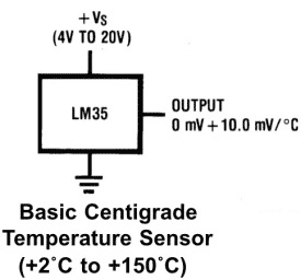
In this tutorial, we are making a Digital Thermometer using PIC microcontroller and LM35 Temperature Sensor. In this project, we will sense the temperature using LM35 and display it on 16x2 LCD. LM35 Temperature Sensor is accurate and cheaper and doesn’t require any external calibration. The output voltage is proportional to Celsius temperature scale and changes by 10mV per °C.
Material Required
- PicKit 3
- LM35 Temperature Sensor
- 16*2 LCD
- PIC16F877A IC
- 40 - Pin IC holder
- Perf board
- 20 MHz Crystal OSC
- Female and Male Bergstick pins
- 33pf Capacitor - 2Nos, 100uf and 10uf cap.
- 680 ohm, 220 ohm, 10K and 560ohm Resistor
- Potentiometer 10k
- LED of any color
- 1 Soldering kit
- IC 7805
- 12V Adapter
- Connecting wires
- Breadboard
LM35 Temperature Sensor:
LM35 temperature sensor has zero offset voltage, which means at 0°C the output will be 0V. The maximum voltage it can handle is 1.5V which means it can be able to sense a maximum temperature of 150°C (1.5V / 10mV).
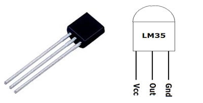
| Pin No | Function | Name |
| 1 | Supply voltage; 5V (+35V to -2V) | Vcc |
| 2 | Output voltage (+6V to -1V) | Output |
| 3 | Ground (0V) | Ground |
We have already used LM35 with many other microcontrollers to measure the temperature:
- Digital Thermometer using LM35 and 8051 Microcontroller
- Temperature Measurement using LM35 and AVR Microcontroller
- Digital Thermometer using Arduino and LM35 Temperature Sensor
- Room Temperature Measurement with Raspberry Pi
As we already told that LM35 gives analog output, so first we need to read that analog values using PIC Microcontroller and then we will convert them into digital values using ADC (Analog to Digital Conversion). So we will learn ADC in PIC Microcontroller before going any further.
ADC in PIC Microcontroller PIC16F877A:
There are many types of ADC available and each one has its own speed and resolution. The most common types of ADCs are flash, successive approximation, and sigma-delta. The type of ADC used in PIC16F877A is called as the Successive approximation ADC or SAR in short. So let’s learn a bit about SAR ADC before we start using it.
Successive Approximation ADC: The SAR ADC works with the help of a comparator and some logic conversations. This type of ADC uses a reference voltage (which is variable) and compares the input voltage with the reference voltage using a comparator and difference, which will be a digital output, is saved from the Most significant bit (MSB). The speed of the comparison depends on the Clock frequency (Fosc) on which the PIC is operating.
Now that we know some basics on ADC, lets open our datasheet and learn how to use the ADC on our PIC16F877A MCU. The PIC we are using has 10-bit 8-channel ADC. This means the output value of our ADC will be 0-1024 (2^10) and there are 8 pins (channels) on our MCU which can read analog voltage. The value 1024 is obtained by 2^10 since our ADC is 10 bit. The eight pins which can read the analog voltage are mentioned in the datasheet. Lets look at the picture below.
The analog channels AN0 to AN7 are highlighted for you. Only these pins will be able to read analog voltage. So before reading an input voltage we have to specify in our code which channel has to be used to read the input voltage. In this tutorial we will use channel 4 with a potentiometer to read the analog voltage at this channel.
The A/D module has four registers which has to be configured to read data from the Input pins. These registers are:
• A/D Result High Register (ADRESH)
• A/D Result Low Register (ADRESL)
• A/D Control Register 0 (ADCON0)
• A/D Control Register 1 (ADCON1)
Learn more about ADC in PIC Microcontroller here.

Code and Explanation
The complete code for this Digital Thermometer using LM35 and PIC microcontroller is given at the end. The code is self-explained with comment lines and just involves the concept of interfacing a LCD with PIC Microcontroller and Using ADC module in PIC Microcontroller which we have already covered in our previous tutorials of learning PIC Microcontrollers.
Here we are just showing the calculations done for reading the analog output voltage from LM35 and then converting it into temperature values. So here we are converting the ADC value from LM35 into the voltage and then voltage value into temperature. Therefore, after getting the value we have seperated every character for displaying on LCD.
        adc = (ADC_Read(4)); // Reading ADC values
        volt = adc*4.88281; // Convert it into the voltage
        temp=volt/10.0;  // Getting the temperature values
        temp1 = temp*100;
        c1 = (temp1/1000)%10;
        c2 = (temp1/100)%10;
        c3 = (temp1/10)%10;
        c4 = (temp1/1)%10;
Now in the below code, set the LCD cursor and then print the output value
        Lcd_Clear();
        Lcd_Set_Cursor(1,3);
        Lcd_Print_String("Temperature");
        Lcd_Set_Cursor(2,5);
        Lcd_Print_Char(c1+'0');
        Lcd_Print_Char(c2+'0');
        Lcd_Print_String(".");
        Lcd_Print_Char(c3+'0');
        Lcd_Print_Char(c4+'0');
        Lcd_Print_Char(0xDF);
        Lcd_Print_String("C");
        __delay_ms(3000);
Working of Digital Thermometer
After uploading the code in the PIC micro-controller, power up the circuit using 12v adapter. The analog output of LM35 temperature sensor is fed to the analog input channel of the PIC controller. As the temperature increase the ADC value will also increase. That ADC value is further converted into voltage by multiplying it with 4.88281. Then the voltage value is converted to corresponding character for displaying it into 16*2 LCD.
Complete Project Code
#define _XTAL_FREQ 20000000
#define RS RD2

#define EN RD3

#define D4 RD4

#define D5 RD5

#define D6 RD6

#define D7 RD7
#include <xc.h>
#pragma config FOSC = HS        // Oscillator Selection bits (HS oscillator)

#pragma config WDTE = OFF       // Watchdog Timer Enable bit (WDT disabled)

#pragma config PWRTE = ON       // Power-up Timer Enable bit (PWRT enabled)

#pragma config BOREN = ON       // Brown-out Reset Enable bit (BOR enabled)

#pragma config LVP = OFF        // Low-Voltage (Single-Supply) In-Circuit Serial Programming Enable bit (RB3 is digital I/O, HV on MCLR must be used for programming)

#pragma config CPD = OFF        // Data EEPROM Memory Code Protection bit (Data EEPROM code protection off)

#pragma config WRT = OFF        // Flash Program Memory Write Enable bits (Write protection off; all program memory may be written to by EECON control)

#pragma config CP = OFF         // Flash Program Memory Code Protection bit (Code protection off)
void ADC_Initialize()

{

  ADCON0 = 0b01000001; //ADC ON and Fosc/16 is selected

  ADCON1 = 0b11000000; // Internal reference voltage is selected

}
unsigned int ADC_Read(unsigned char channel)

{

  ADCON0 &= 0x11000101; //Clearing the Channel Selection Bits

  ADCON0 |= channel<<3; //Setting the required Bits

  __delay_ms(2); //Acquisition time to charge hold capacitor

  GO_nDONE = 1; //Initializes A/D Conversion

  while(GO_nDONE); //Wait for A/D Conversion to complete

  return ((ADRESH<<8)+ADRESL); //Returns Result

}

//LCD Functions Developed by Circuit Digest.

void Lcd_SetBit(char data_bit) //Based on the Hex value Set the Bits of the Data Lines

{

    if(data_bit& 1)

        D4 = 1;

    else

        D4 = 0;
    if(data_bit& 2)

        D5 = 1;

    else

        D5 = 0;
    if(data_bit& 4)

        D6 = 1;

    else

        D6 = 0;
    if(data_bit& 8)

        D7 = 1;

    else

        D7 = 0;

}
void Lcd_Cmd(char a)

{

    RS = 0;

    Lcd_SetBit(a); //Incoming Hex value

    EN  = 1;

        __delay_ms(4);

        EN  = 0;

}
Lcd_Clear()

{

    Lcd_Cmd(0); //Clear the LCD

    Lcd_Cmd(1); //Move the curser to first position

}
void Lcd_Set_Cursor(char a, char b)

{

    char temp,z,y;

    if(a== 1)

    {

      temp = 0x80 + b - 1; //80H is used to move the curser

        z = temp>>4; //Lower 8-bits

        y = temp & 0x0F; //Upper 8-bits

        Lcd_Cmd(z); //Set Row

        Lcd_Cmd(y); //Set Column

    }

    else if(a== 2)

    {

        temp = 0xC0 + b - 1;

        z = temp>>4; //Lower 8-bits

        y = temp & 0x0F; //Upper 8-bits

        Lcd_Cmd(z); //Set Row

        Lcd_Cmd(y); //Set Column

    }

}
void Lcd_Start()

{

  Lcd_SetBit(0x00);

  for(int i=1065244; i<=0; i--)  NOP();

  Lcd_Cmd(0x03);

    __delay_ms(5);

  Lcd_Cmd(0x03);

    __delay_ms(11);

  Lcd_Cmd(0x03);

  Lcd_Cmd(0x02); //02H is used for Return home -> Clears the RAM and initializes the LCD

  Lcd_Cmd(0x02); //02H is used for Return home -> Clears the RAM and initializes the LCD

  Lcd_Cmd(0x08); //Select Row 1

  Lcd_Cmd(0x00); //Clear Row 1 Display

  Lcd_Cmd(0x0C); //Select Row 2

  Lcd_Cmd(0x00); //Clear Row 2 Display

  Lcd_Cmd(0x06);

}
void Lcd_Print_Char(char data)  //Send 8-bits through 4-bit mode

{

   char Lower_Nibble,Upper_Nibble;

   Lower_Nibble = data&0x0F;

   Upper_Nibble = data&0xF0;

   RS = 1;             // => RS = 1

   Lcd_SetBit(Upper_Nibble>>4);             //Send upper half by shifting by 4

   EN = 1;

   for(int i=2130483; i<=0; i--)  NOP();

   EN = 0;

   Lcd_SetBit(Lower_Nibble); //Send Lower half

   EN = 1;

   for(int i=2130483; i<=0; i--)  NOP();

   EN = 0;

}
void Lcd_Print_String(char *a)

{

    int i;

    for(i=0;a[i]!='\0';i++)

       Lcd_Print_Char(a[i]);  //Split the string using pointers and call the Char function

}

int main()

{

    float adc;

    float volt, temp;

    int c1, c2, c3, c4, temp1;

    ADC_Initialize();
    unsigned int a;

    TRISD = 0x00;

    Lcd_Start();

    while(1)

    {

        adc = (ADC_Read(4)); // Reading ADC values

        volt = adc*4.88281; // Convert it into the voltage

        temp=volt/10.0;  // Getting the temperature values

        temp1 = temp*100;


        c1 = (temp1/1000)%10;

        c2 = (temp1/100)%10;

        c3 = (temp1/10)%10;

        c4 = (temp1/1)%10;


        Lcd_Clear();

        Lcd_Set_Cursor(1,3);

        Lcd_Print_String("Temperature");

        Lcd_Set_Cursor(2,5);

        Lcd_Print_Char(c1+'0');

        Lcd_Print_Char(c2+'0');

        Lcd_Print_String(".");

        Lcd_Print_Char(c3+'0');

        Lcd_Print_Char(c4+'0');

        Lcd_Print_Char(0xDF);

        Lcd_Print_String("C");

        __delay_ms(3000);

    }

    return 0;

}
Comments
I don't think I followed what you tried to achieve here(ADCON0...ADCON2 is really complex topic I guess ), with the following code section:
unsigned int ADC_Read(unsigned char channel)
{
ADCON0 &= 0x11000101; //Clearing the Channel Selection Bits
ADCON0 |= channel<<3; //Setting the required Bits
....
I refereed to the manual and tried to implement the same on PIC18F4620 but without success.
I edited the ADC_Initialization section to match a 18F4620 :
void ADC_Initialize()
{
ADCON0 = 0b00000001;//ref page 223-225 DataSheet
ADCON1 = 0b00000001;
ADCON2 = 0b10111101;
}
But, I must be missing something in the clearing bit section...as i am getting 10-20 as ADC or 48mV volts even if I connect channel 4 to 5VDC supply.
Please advise.
Thanks
DDA
Hi,
I got it figured out, Tutorial 9 was helpful in that regard ( https://circuitdigest.com/microcontroller-projects/pic-microcontroller-pic16f877a-adc-tutorial).
For others how might be stuck with other processors...here is the modified code section for PIC18F4620 to give you another perspective on the ADC register assignments.
unsigned int ADC_Read(unsigned char channel)
{
ADCON0 &= 0b00000011; //Clearing the Channel Selection Bits, which are bits #2-5 using the & operator...channels are 4bits as it has 13ADC compared to 3bits for 877A which has 8 ADC and bit#are 3-5
ADCON0 |= channel<<2; //Setting the required bits by left shifting twice as ch bits start from 2 and ends in 5 and using "|" or operator.
//ADCON2 &= 0x00000011; //Clearing the Channel Selection Bits
__delay_ms(2); //Acquisition time to charge hold capacitor
GO_nDONE = 1; //Initializes A/D Conversion
while(GO_nDONE); //Wait for A/D Conversion to complete
return ((ADRESH<<8)+ADRESL); //Returns Result
}
void ADC_Initialize()
{
ADCON0 = 0b00000001;//set only ADON or AD enable (bit#0) rest leave all as default zero ref page 223-225 DataSheet
ADCON1 = 0b00000010; // Choosing 0010 sets all 13 AD ports analog..rest default 0
ADCON2 = 0b10111101; // set the ADCS2-ADCS0 to 101 , to make it Fosc16 clock, set the TAD to 20 by selecting 111, finally the MSB bit is 1 to make Rt justified data.For 4620 the ADCS2:ADCS0 bits for clock is in the thirs red ADCON2.
}
Hope this helps others with similar problem.
Sir, I am a hobbist having no knowledge of software. Now Working with your Digital Alarm clock. Just now I have burnt the code of the project using winpic programming software sucesfully throurg JDM circuit made by myself. If I put the MCU into the circuit will it work sir.
thanking you sir,
Leelesh

please the code when I test it in micro C it does not work there is a lot of error please help me solve them