
 Meter")
In an ideal scenario, a battery should have zero internal resistance. But batteries are not made perfect and the electrodes are not 100% conductive, which creates a small resistance within the battery called internal resistance. Practically batteries will always have some internal resistance. On paper, the value of the resistance will appear low around 0.1Ω for an AA alkaline battery, about 1Ω for a 9-volt alkaline battery, and 20 to 30mΩ for a lithium polymer battery, it could have a significant impact if a high load is attached to the battery. Know more about different types of batteries. So in this article, we have decided to build a simple Attiny85 Based Battery ISR Meter that will accurately measure the internal resistance of any Lithium cell and display the result on an OLED Display. The complete meter is build on a PCB fabricated by pcbway, more on that will be discussed later in this article.
Previously we have built many different projects on measuring instruments, you can check the list below if you are interested.
- ESP32 Based Power Meter - Measuring Input Power and Output Power to Calculate Efficiency
- Build Your Very Own Low Resistance Meter with Arduino
- DIY LED VU Meter as Arduino Shield
- LC Meter using Arduino: Measuring Inductance and Frequency
- IoT-Based Electricity Energy Meter using ESP12 and Arduino
How Does an Internal Series Resistance(ISR) Meter Work?
So in the introduction part, you know what will be the objective of the project, now the question remains, how do you measure resistance which is inside the battery cell? The answer to this question is simple, we do it with the help of a potential divider or voltage divider! Yes, you heard that right. We will be using a voltage divider and ohm's law formula to measure the internal resistance of the battery. But for that, we need a known value resistor (we are using a 2 OHM resistor) and a multimeter. In the section below, we have shown you how you can do that.
The resistors you can find in the market are not accurate and they have tolerances, which is why the value of the resistor can change depending on the temperature. Now the resistor we are using has a 5% tolerance.
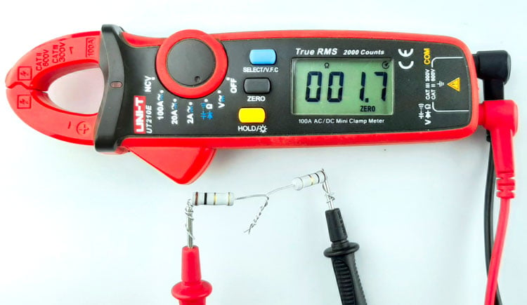
Now as you can see the resistor shown above measures 1.7 Ohms but we need to take into consideration the multimeter tolerance and the resistor tolerance. After considering that we found out that our theoretical 2 ohms resistor has a resistance value of 1.2 Ohms so we'll be using the 1.2 Ohms value in the calculation.
Note: Multimeters are not usually good at measuring resistance but what they are good at is measuring voltage. So what you can do is use a constant current source to flow 500mA or 1A through the resistors and measure the voltage drop across the resistor. This way you can get a pretty decent measurement of the resistance.
Now we need to measure the no-load voltage of the battery, as you can see in the image below.
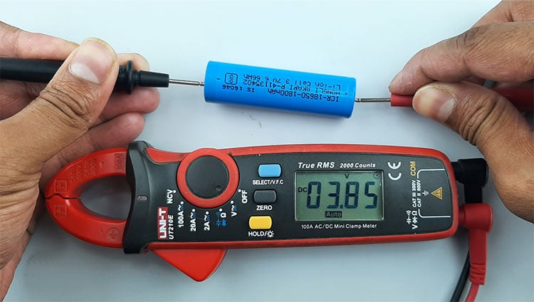
The battery voltage is 3.85 volts. Now we need to calculate the theoretical current that will flow through the resistor if we connect it with the battery, for that we are going to be using Ohm's law.
Current through the resistor I = V/R,
I = 3.85/1.2 =3.236 Amps
if we connect the resistor to the battery, 3.22 Amps will be drawn by the 1.2 Ohm resistor. When the load is connected we also need to measure the voltage.
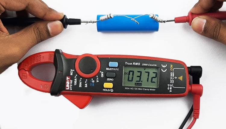
You can see in the image above, the load Voltage is Vload = 3.72. We need to subtract these two voltage values, the open circuit voltage, and the load voltage. If we do that, we will get the voltage drop across the internal resistance.
Vinternal = 3.85-3.72 = 0.13V
Now we have the voltage drop across the internal resistor, we can just divide it with the calculated current and we will get the internal resistance.
ISR = (Vdrop-internal / Current) = 0.13/3.236 = 0.04017 ohms
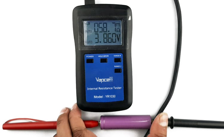
The calculated internal resistance of the battery is 0.04017 mOhms. Let's test our calculated voltage with the professional meter bought from the market.
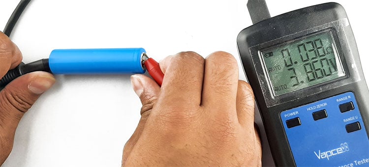
As you can see in the image above, we are pretty close to the measured value by the professional ISR meter.
Note: When you are using this method to measure the internal resistance of the battery using Arduino, you need to consider the internal resistance of the MOSFET and the resistance of the PCB copper traces. Some MOSFETS are not fully on at 5V so you need to consider all those in your code and calibrate the code according to that value.
Components Required to Build the ISR Meter
The components required to build the ATtiny85-based ISR meter are listed below. We designed this circuit with very generic components, which makes the replication process very easy.
- Attiny85 Microcontroller - 1
- LM358 Op-amp - 1
- 1R Resistor -2
- Low VGS Mosfet - 1
- Push-Button - 1
- Oled Module 128X64
- Battery Holder
- Capacitor 0.1uF
- Resistor 1K - 1
ISR Meter Circuit Diagram
The complete circuit diagram of the ATtiny85 microcontroller-based ISR Meter is shown below.

The schematic diagram ISR meter circuit is very simple. We have divided the schematic diagram into sections so that you can easily understand different parts of the schematic easily.
First, let's discuss the Battery Current Controller Section. The main objective of the circuit is to protect the MOSFET against high peak currents. As you can see in the non-inverting terminal (pin3) of the op-map, we have an input PWM signal from the microcontroller. The signal gets filtered out by a 100nF capacitor and a 100K resistor and the filtered DC signal goes to the pin3 of the OP-amp. Now the voltage at the non-inverting terminal is greater than the inverting terminal, the output of the op-amp goes high. The high output of the op-amp switches the state of the MOSFET on and current starts to flow through it and the Resistor(R1). Now when the current starts flowing there will be a voltage drop across the resistor R1. If the value of that voltage is greater than the value at the non-inverting terminal, the output of the op-amp will go low and the current will stop flowing. This process will continue until the PWM output goes to zero.
The brain of the project is the ATtiny85 microcontroller that provides the PWM signal to drive the op-amp and it also measures the battery voltage to calculate the IR of the battery. other than that, we have a USB connector. The USB connector is there to program the board and provide power to the microcontroller. We have an OLED module to display the ISR Value and the battery voltage. Also, we have a battery connector and a switch. The battery connector is to place the battery under test and the switch is there to reset the microcontroller.
PCB Design of the ATtiny85 Based ISR Meter
To make our life a little bit easier, we decided to make a PCB for the project.

As you can see in the above image, the PCB is designed with EAGLE PCB design software and it has a dimension of 90mm X 55mm. If you want to recreate the project yourself, you can download the Gerber files and order the PCB for yourself.
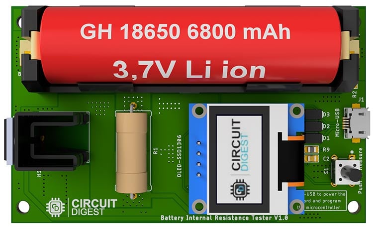
Top Side of the ISR Meter PCB

The 2D image of the PCB is shown above. It is a double-layer PCB with proper ground reference. We have placed all the components on the top side of the PCB and on the bottom side, only the connections are there.
Bottom Side of the ISR Meter PCB

The bottom side of the PCB is shown above and as you can see, we don't have any components on the back side and there are four mounting holes there in the PCB.
3D model of the ISR Meter PCB
The 3D model of the ISR meter PCB is shown above. In the 3D model, you can see the placement of all the components including the heat sink, the 5W resistor micro USB, and the switch. The opamp and the microcontroller are at the bottom of the LCD.
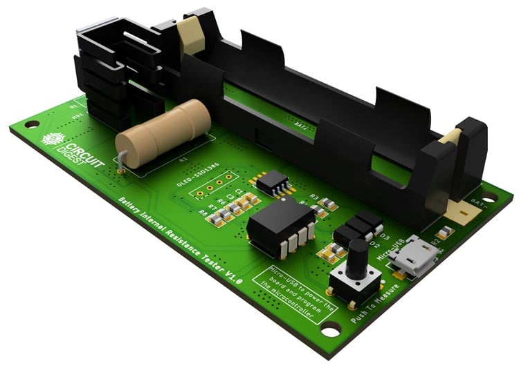
In the image above you can see the placement of the op-amp and the microcontroller.
Ordering the Internal Series Resistance Meter PCB from PCBWay
After finalizing the design, you can proceed with ordering the PCB:
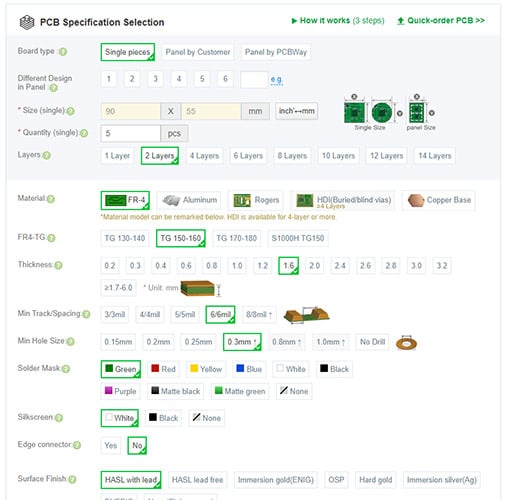
Step 1: Go to www.pcbway.com, and sign up if this is your first time. Then, in the PCB Prototype tab, enter the dimensions of your PCB, the number of layers, and the number of PCBs you require.
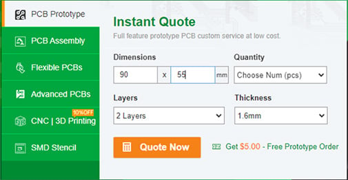
Step 2: Proceed by clicking on the ‘Quote Now’ button. You will be taken to a page where you need to set a few additional parameters like the Board type, Layers, Material for PCB, Thickness, and more. Most of them are selected by default, but if you opt for specific parameters, you can select them here.
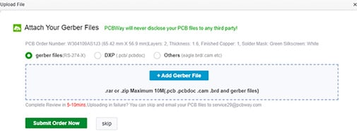
Step 3: The final step is to upload the Gerber file and proceed with the payment. To make sure the process is smooth, PCBWAY verifies if your Gerber file is valid before proceeding with the payment. This way, you can be sure that your PCB is fabrication-friendly and you will receive it as committed.
Assembling the ATtiny85 Based ISR Meter PCB
After a few days, we received our PCB in a neat package and the PCB quality was good as always. The top layer and the bottom layer of the board are shown below:
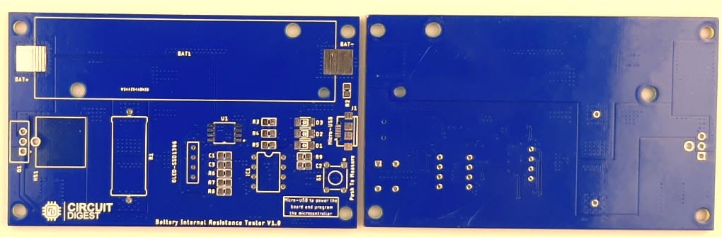
After making sure the tracks and footprints were correct, I proceeded with assembling the PCB. The image here shows what the completely soldered board looks like.
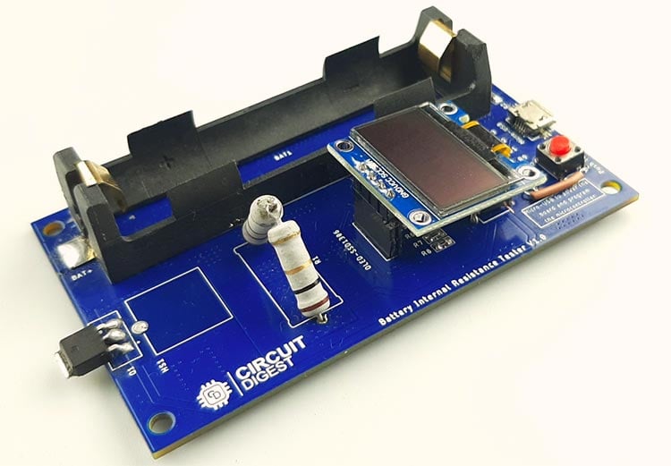
As you can see in the image, all the components are soldered properly. As mentioned earlier, all the components for this project are easily available so the replication of the project is very easy. You can also download the Gerber File so you can order your PCB if you need to.
Arduino Code to Program the Onboard Attiny85 Microcontroller
The code for this project is extremely simple and easy to understand. But before we start our project, we need to download the SSD1306_minimal header file and put it inside our code folder. Once we do that we can start our code process.
We start our code by including all the required libraries. There are only two libraries that we need to include and those are:
#include "SSD1306_minimal.h"
#include <avr/pgmspace.h>
Next, we create an instance for SSD1306_minimal through which we can access all the functions simultaneously.
SSD1306_Mini oled
Next, we have defined all the pins and the variables for the project.
//#define OLED_RESET  4                       // OLED reset pin
#define vIn   A2                           // raw battery voltage
#define gate    1                       // xsistor base pin
float v1 = 0.000;                               // unloaded battery voltage
float v2 = 0.000;                               // loaded battery voltage
float i = 0.000;                               // unloaded current                              // loaded current
float intRes = 0.000;                           // battery internal resistance in Ohms
float vCal = 4.97;                             // calculated vRef (measure between 5V & Gnd)
float load_resistance = 2;                                   // load resistance in Ohms
Next, we have our setup function, in the setup function, we have set the analog pin as input and the PWM pin as output and also set that to low to prevent false triggering. Next, we initialize the display with the I2C address of the display and we clear the display. Then we call the measure_value() and end the setup() function.
void setup() {
  //  Serial.begin( 9600 );
  pinMode(vIn, INPUT);                      // set A0 as input
  pinMode(gate, OUTPUT);                   // set D9 as output
  digitalWrite(gate, LOW);
  delay(100);
  oled.init(0x3C); // Initializes the display to the specified address
  oled.clear(); // Clears the display
  delay(1000); // Delay for 1 second
  measure_value();
  //print_to_screen();
}
Finally, we have the measure_value() function in which we call the startscreen() method to clear the display.
  oled.startScreen();
  oled.clear(); // Clears the display
Next, we measure the unloaded voltage and calculate the theoretical current through the resistor and print it to the display.
  char buff[10];
  v1 = (analogRead(vIn) * vCal) / 1023;
  delay(5);
  dtostrf(v1, 4, 3, buff);
  oled.cursorTo(0, 0); // x:0, y:0
  oled.printString("  Voltage1:");
  oled.printString(buff);
  i = (v1 / load_resistance);
  dtostrf(i, 4, 3, buff);
  oled.cursorTo(0, 10); // x:0, y:0
  oled.printString("  Current:");
  oled.printString(buff);
Then, we make the PWM pin of the microcontroller high and calculate the load voltage across the resistor.
digitalWrite(gate, HIGH);
  delay(5);
  v2 = (analogRead(vIn) * vCal) / 1023;
  delay(1);
  dtostrf(v2, 4, 3, buff);
  oled.cursorTo(0, 20); // x:0, y:23
  oled.printString("  Voltage2:");
  oled.printString(buff);
  delay(3);
  digitalWrite(gate, LOW);
Now we have all the required values and we can calculate the internal series resistance of the battery.
  intRes = (((v1 - v2) / i) + 0.017);
  dtostrf(intRes, 4, 3, buff);
  oled.cursorTo(0, 30); // x:0, y:23
  oled.printString("  IntRes:");
  oled.printString(buff);
This is the end of the code portion of the Arduino. If you have difficulty understanding the code, you can refer to the above section in the code.
Testing the AVR ATtiny85 Microcontroller based ISR Meter
Once the assembly of the PCB was done and the code was uploaded, we started testing the PCB. First, we powered up the PCB and checked to see if the op-amp pin and the microcontroller pin were getting 5V and we also made sure that there were no short circuits on the board.
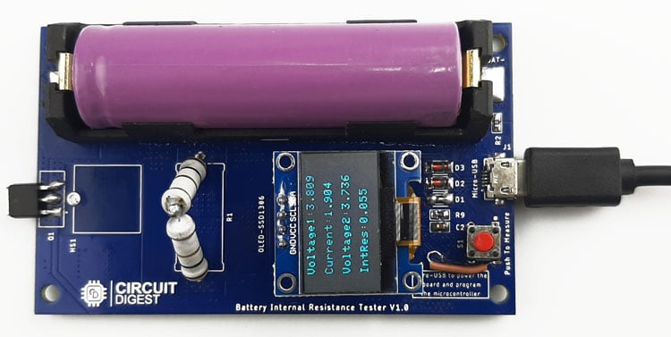
Once the code is uploaded, you can see it gives us the resistance value in milliohms and for the accuracy test we have compared it to a professional meter and the result of that is shown below.
As you can see in the above two images, our meter can active pretty decent results when it comes to accuracy.
Problems we found and the solution we have come up with while testing the PCB board.
The PCB we made was not perfect and found some problems while we were working with it.
The first problem we found was the problem in the MOSFET. While placing the MOSFET, the connection got mirrored so we need to connect the MOSFET in the opposite direction.
The next problem was also regarding the MOSFET. In order for the MOSFET to turn on, we need MOSFETS like IRLZ44N, IRF540 but at the moment of building the project, we don't have those values, so we had to put a SMD MOSFET in place of the TO-220 one.
The next major problem is with the power section of the board. You see the main power for the board comes from the USB cable and depending upon the cable length, the voltage value varies. Now as the ADC accuracy depends upon the input voltage, the error rate goes very high.
Next, we have the programming issue, while building the PCB we didn't put programming header on the board so now to program the microcontroller for the first time, you need to solder wires to the pins of the microcontroller or you need a SMD ZIF Socket to program.
This meter is not able to measure the internal resistance if the battery voltage is below 3 volts.
Complete Project Code
#include "SSD1306_minimal.h"
#include <avr/pgmspace.h>
SSD1306_Mini oled;
//#define OLED_RESET  4                       // OLED reset pin
#define vIn   A2                           // raw battery voltage
#define gate    1                       // xsistor base pin
float v1 = 0.000;                               // unloaded battery voltage
float v2 = 0.000;                               // loaded battery voltage
float i = 0.000;                               // unloaded current                              // loaded current
float intRes = 0.000;                           // battery internal resistance in Ohms
float vCal = 4.97;                             // calculated vRef (measure between 5V & Gnd)
float load_resistance = 2;                                   // load resistance in Ohms
void setup() {
  //  Serial.begin( 9600 );
  pinMode(vIn, INPUT);                      // set A0 as input
  pinMode(gate, OUTPUT);                   // set D9 as output
  digitalWrite(gate, LOW);
  delay(100);

  oled.init(0x3C); // Initializes the display to the specified address
  oled.clear(); // Clears the display
  delay(1000); // Delay for 1 second

  measure_value();
  //print_to_screen();
}
void loop() {

  //  oled.startScreen();
  //  oled.clear(); // Clears the display
  //  //int  sensorValue = analogRead(4);
  //
  //  analogResult = analogRead(A2);
  //
  //  char buff[10];
  //
  //  dtostrf(analogResult, 4, 3, buff);
  //  oled.cursorTo(0, 0); // x:0, y:0
  //  oled.printString("  Voltage1:");
  //  oled.printString(buff);
  //
  //  //analogWrite(gate, 255);
  //  int value;
  //  float volt;
  //  //
  //  //    value = analogRead( vIn );
  //
  //  // volt = value * 4.68 / 1023.0;
  //  ////
  //  //    Serial.print( "Value: " );
  //  //    Serial.print( value );
  //  //    Serial.print( "  Volt: " );
  //  //    Serial.println( volt );
  //  //
  //
  delay(1);
}
float measure_value()
{
  oled.startScreen();
  oled.clear(); // Clears the display
  char buff[10];
  v1 = (analogRead(vIn) * vCal) / 1023;
  delay(5);
  dtostrf(v1, 4, 3, buff);
  oled.cursorTo(0, 0); // x:0, y:0
  oled.printString("  Voltage1:");
  oled.printString(buff);
  i = (v1 / load_resistance);
  dtostrf(i, 4, 3, buff);
  oled.cursorTo(0, 10); // x:0, y:0
  oled.printString("  Current:");
  oled.printString(buff);
  digitalWrite(gate, HIGH);
  delay(5);
  v2 = (analogRead(vIn) * vCal) / 1023;
  delay(1);
  dtostrf(v2, 4, 3, buff);
  oled.cursorTo(0, 20); // x:0, y:23
  oled.printString("  Voltage2:");
  oled.printString(buff);
  delay(3);
  digitalWrite(gate, LOW);
  intRes = (((v1 - v2) / i) + 0.017);
  dtostrf(intRes, 4, 3, buff);
  oled.cursorTo(0, 30); // x:0, y:23
  oled.printString("  IntRes:");
  oled.printString(buff);
}Comments
The above comment was based from the values shown in the video. With your PWM circuit , you could use that circuit as a constant current source. In that case you would leave the resistor where it is in the source of the mosfet. You could then set the current to what ever you want by setting the PWM value. PWM of 50% = 2.5V , current would then be 2.5/2 = 1.25A.
You do not however seem to be doing this in you code. You are driving the pin with a logic signal. If that's how the circuit is going to work , then move the load resistor to the drain , and your calculations will be more accurate.

Nice project.
A few things you should change. Your calculation of the battery current should be using V2 , not V1. V1 is the open circuit voltage , you need to use the loaded voltage to get the current. In the video that would be 3.78V / 2R = 1,89A.
Connect your load resistor onto the drain side of the mosfet. That way the volt drop across the load resistor does not try and turn off your mosfet. If you have a gate drive of 5V and your current in the load resistor is 1.89A , then the source voltage will rise up to 3.78V. Your mosfet will now be in it's linear region and it's resistance will be much higher. It will also get VERY hot :0)
If the load resistor is in the Drain circuit , the mosfet will still see the full 5V across the gate-source and will be turned on much better.
Cheers
Robin