

If you are a maker like me and looking for some interesting projects online, a milliohm meter is one easy and useful thing you can make. The basic principle of this circuit is based around a constant current source, which we have covered in one of our previous articles. A milliohm meter is a device that can be used to determine the values of small resistors, the resistance of PCB traces, and if you are aware of the know-how, it can be used to find out a short circuit in the PCB.
There are a lot of milliohm meter and low resistance meter circuits out there on the internet, but today we will use an Arduino and the popular LM317 linear regulator IC to make a very simple low resistance meter, which is not only reliable but also gives an accurate measurement. W will also display the information on an OLED display and at the end, we will do a performance test of our circuit. This circuit is not only accurate but also has a decent range, in our testing. We were able to measure 0.05R to 22R pretty accurately. So without further ado, let’s get started.
At this point, if you are looking for a meter that can measure large resistance values, you can check our previous project on Arduino Based Ohm Meter.
What is a Milliohm meter and how does it work?
As we have discussed earlier, a milliohm meter is a device that is used to measure low resistance and if you are asking why it’s important to measure low resistance, let me tell you it can be used in many different types of applications other than measuring resistance. An example could be like; suppose you have a circuit board that shows a short circuit in the power section, most of the time, the problem can be a bad capacitor. If you have a low resistance meter at your disposal, you can check different parts of your circuit board in order to pinpoint a particular region where the resistance is lowest, then you can start debugging from there. This was a simple example if you want you could do more than just this.
Resistance can be defined as a component that opposes the flow of electrons; the unit of resistance is ohms. A milliohm meter is a very simple instrument used to measure unknown / low-value resistances. There are many ohmmeters available in the market and they can measure a wide range of resistances, but those meters have one thing in common, they are pretty expensive, to begin with.
Our milliohm meter works on the principle of Ohm's Law. the working principle and the circuitry are very simple, as you already know from the title, we are going to use an Arduino to process the current information, but the Arduino doesn’t know how to measure current, it only knows how to measure voltage, to convert the current value to voltage value, we are going to use a constant current source in conjunction with Ohm's Law, and we will be using the popular LM317 Regulator for the constant current source.
Components Required to Build the Arduino Based Low Resistance Meter
You need a handful of components to build this project, as they are very generic you can find all of them in your local hobby store. A list of components with values is given below.
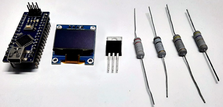
- Arduino Nano - 1
- LM317T - 1
- 128 X 64 OLED - 1
- 10 R Resistor - 1
- Test Resistors
Schematic Diagram of the Arduino Based Low Resistance Meter
The complete circuit diagram of the Arduino Based Low Resistance Meter is shown below.

The connection diagram and the working principle of this circuit are very simple, as you can see in the above schematic, we have an Arduino Nano which is responsible for data collection, calculation, and processing. We have an OLED display that shows the calculated resistance value. And finally, we are using an LM317T which is the constant current source. With the constant current source and a little bit of ohm's law, we can calculate the resistance value quite easily.
In the schematic, you can see a formula that is used to calculate the current limit for the LM317 Regulator IC. As you can also see in the schematic, we have used a 10R resistor with the circuit to calculate a constant current of 0.125A or 125mA. Now, as we have the current value, we just need to divide that with voltage to get the Resistance V=IR so R =V/I, and we will get the resistance.
Code: Arduino Based Low Resistance Meter
The complete code used in this project can be found at the bottom of this page. After adding the required header files and source files, you should be able to directly compile the Arduino code. You can download the libraries from the link given below or else you can use the board manager method to install the library.
The code is very simple, and it goes as follows. We start by including all the required libraries. As we are using an OLED display, we have to include the SSD1306 library and the Wire library, the SSD1306 library uses the wire library.
#include <Adafruit_SSD1306.h>
#include <Wire.h> // Wire Library for OLED
Next, we will define the screen width and screen height for the display. Also, we will define the resistance value, and the reference value for the LM317 regulator IC. This is required because we will calculate the constant current with these values. Once we do that, we will define all the necessary variables required for averaging the ADC values. Also, we will declare the pin no and other variables.
const int numReadings = 50; // used for averaging / we will take 50 samples and average it to get ADC value
int readings[numReadings]; // Store the readings from the analog input
int readIndex = 0; // the index of the current reading
int total = 0; // the running total
int ADCaverage = 0; // the average
float R; // Stores the Resistance Value
int inputPin = A0; // A0 is selected as input
Next, we create an instance for the SSD1306 display and pass in the wire object.
Adafruit_SSD1306 display(SCREEN_WIDATA_PINH, SCREEN_HEIGHT, &Wire, -1);
Next, in the setup () section, we will initialize the display and check if the display is available or not. We do that with the help of an if statement. If the display is available, we move forward to our code, else we print an error statement.
 if (!display.begin(SSD1306_SWITCHCAPVCC, 0x3C)) { // Address 0x3D for 128x64
    Serial.println(F("SSD1306 allocation failed"));
    for (;;);
  }
Next, we set the text colour of the OLED display, if we don't then there is a chance that the display will show black segments. Then we rotate the display with the help of the display.setRotation(2) method as this is a requirement for this project. Once done, we define the for loop. Inside the for loop, we initialize all the elements of the array to zero. This is important because there can be garbage values inside the array that can introduce errors with our calculations.
display.setTextColor(WHITE); // set LCD Colour
  display.setRotation(2); // it has modes 1,2,3,4
  //
  for (int thisReading = 0; thisReading < numReadings; thisReading++) {
    readings[thisReading] = 0;
  }
delay(500);
}
Next, we have our loop () section. In this section, we do all the necessary calculation that is required to average the ADC value for smoothing the output ADC reading. The code you see below is used to average the ADC value.
 total = total - readings[readIndex];  // subtract the last reading:
 readings[readIndex] = analogRead(inputPin); // read from the sensor:
  total = total + readings[readIndex];  // add the reading to the total:
  readIndex = readIndex + 1; // advance to the next position in the array:
  if (readIndex >= numReadings) {
    // if we're at the end of the array...
    // ...wrap around to the beginning:
    readIndex = 0;
  }
Once the ADC value is averaged, we print the average value just for debugging. Next, we convert the ADC value to voltage value, as this is required for calculation. Thereafter, we print the voltage value for debugging. Once we have the voltage, we know our current value is fixed. Now, with the help of OHMs law, we calculate the Resistance value and print it in the serial monitor window. Also, we print the values on the OLED display.
 ADCaverage = total / numReadings; // calculate the average:
  Serial.print("AVG: ");
  Serial.print(ADCaverage);
  float voltage = ADCaverage * (5.0 / 1024.0); // Convert ADCaverage to Voltage
  Serial.print(" \t \t"); // give me a little TAb would ya
  Serial.print(voltage, 3); // Print Voltage to Serial Monitor
  Serial.print(" \t \t");// give me another little TAb would ya
  R = voltage / (LM317_REF / LM317_Resistance) ;
  Serial.print("Resistance: ");
  Serial.println(R);
  display.clearDisplay();
  display.setTextSize(2);
  display.setCursor(10, 10);
  display.print(R,3);
  display.print(" R");
  display.display();
  delay(50);
This marks the end of our coding process and now we can move onto testing our meter.
Testing of the Arduino Based Low Resistance Meter
To test this circuit, the following setup is used. The setup is made on a breadboard for testing purposes only, and it's highly recommended to make this circuit on a proper PCB board.
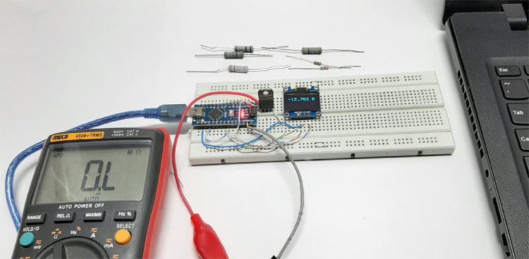
As you can see in the picture, we have made the circuit on a breadboard as it was a test circuit, and it turned out to be a bad idea because the contact resistance and impedance were taking a heavy toll on the circuit. This is why at the last moment, we decided to solder some wires directly on the circuit board, we also soldered the 10R resistance and the wire of the alligator clip directly onto the LM317 IC itself.
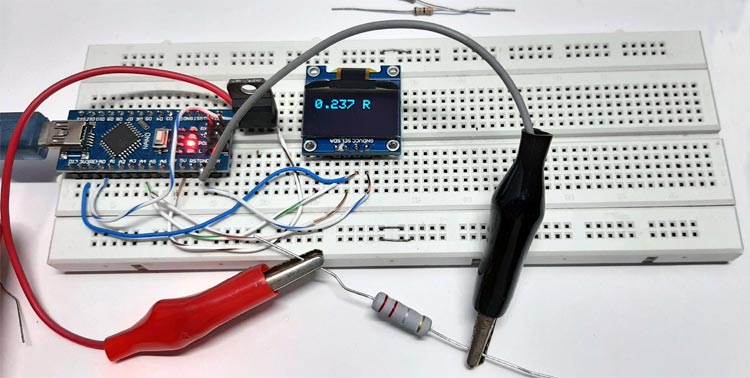
Once we were done with that, we measured some resistances with this meter and observed the results, and the results were pretty good. As you can see in the above image, the value is very spot on.
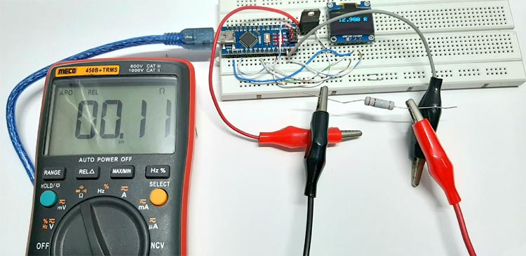
To verify the results, we decided to test the circuit again with the help of our MECHO 450B+ Multimeter and the results were pretty bad. The Multimeter gave us pretty odd values and probably it was an error. To verify, we again tested different resistor values and the result was pretty much the same. At this point, we were sure that the Meco Multimeter was unable to measure such low resistance values. You can check out the video in the description for more details.
Further Enhancements
This circuit is not perfect and it has a lot of room for improvement. First, the circuit needs to be in a perfboard or a piece of PCB board, otherwise, we will have all sorts of problems. We have used the LM317 IC to make the constant current source that can be upgraded to a specific constant current source that is designed for this purpose. We used resistance with 5% tolerances but using resistance with a tolerance of 1% or less will improve the results very much.
With that being said, it's time to end this project. I hope you enjoyed the article and learned something new. If you have any questions regarding the article, you can comment down below else you can post it to our forum for quick response.
Complete Project Code
#include <Adafruit_SSD1306.h>
#include <Wire.h> // Wire Library for OLED
#define SCREEN_WIDATA_PINH 128 // OLED display Width, in pixels
#define SCREEN_HEIGHT 64 // OLED display height, in pixels
#define LM317_REF 1.25
#define LM317_Resistance 10.1
const int numReadings = 50; // used for averaging / we will take 50 samples and average it to get ADC value
int readings[numReadings];      // the readings from the analog input
int readIndex = 0;              // the index of the current reading
int total = 0;                  // the running total
int ADCaverage = 0;             // the average
float R;
int inputPin = A0;
Adafruit_SSD1306 display(SCREEN_WIDATA_PINH, SCREEN_HEIGHT, &Wire, -1);
void setup() {
  // put your setup code here, to run once:
  Serial.begin(9600);
  if (!display.begin(SSD1306_SWITCHCAPVCC, 0x3C)) { // Address 0x3D for 128x64
    Serial.println(F("SSD1306 allocation failed"));
    for (;;);
  }
  display.setTextColor(WHITE); // set LCD Colour
  display.setRotation(2); // it has modes 1,2,3,4
  //
  for (int thisReading = 0; thisReading < numReadings; thisReading++) {
    readings[thisReading] = 0;
  }
delay(500);
}
void loop() {
  total = total - readings[readIndex];  // subtract the last reading:
  readings[readIndex] = analogRead(inputPin); // read from the sensor:
  total = total + readings[readIndex];  // add the reading to the total:
  readIndex = readIndex + 1; // advance to the next position in the array:
  if (readIndex >= numReadings) {
    // if we're at the end of the array...
    // ...wrap around to the beginning:
    readIndex = 0;
  }
  ADCaverage = total / numReadings; // calculate the average:
  Serial.print("AVG: ");
  Serial.print(ADCaverage);
  float voltage = ADCaverage * (5.0 / 1024.0); // Convert ADCaverage t0 Voltage
  Serial.print(" \t \t"); // give me a little TAb would ya
  Serial.print(voltage, 3); // Print Voltage to Serial Monitor
  Serial.print(" \t \t");// give me another little TAb would ya
  R = voltage / (LM317_REF / LM317_Resistance) ;
  Serial.print("Resistance: ");
  Serial.println(R);
  display.clearDisplay();
  display.setTextSize(2);
  display.setCursor(10, 10);
  display.print(R,3);
  display.print(" R");
  display.display();
  delay(50);
}Comments
So sad that the schematic diagram doesn't make any sense. That makes the rebuild pretty difficult.

Nice project.
In the schematic, Probably missing connection between ADJ stabilizer (pin 1) and A0 (pin 4) Arduino, no random connection