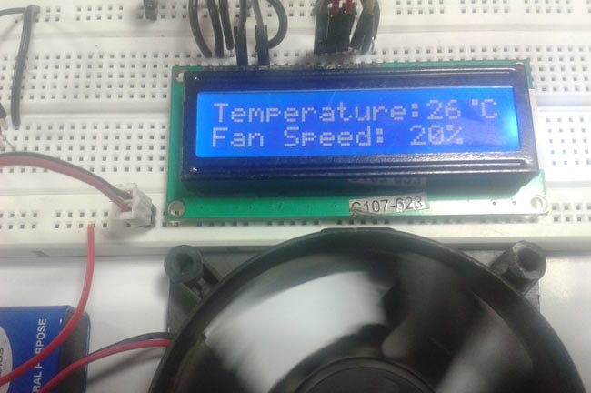
In this arduino based project, we are going to build a temperature-controlled fan using Arduino. With this circuit, we will be able to adjust the fan speed in our home or office according to the room temperature and also show the temperature and fan speed changes on a 16x2 LCD display. To do this we will be using an Arduino UNO Board, LCD, DHT11 sensor Module, and DC fan that is controlled by using PWM. Let's discuss more on this is done so that you can build one on your own. We have also built a project to perform Automatic AC temperature control, you can also check that out if you are intrested.
Components Required
The following are the materials required to perform a temperature-based fan speed control using Arduino. Most of the components should be easily available in your local hardware shop
- Arduino UNO
- DHT11 sensor
- DC Fan
- 2n2222 transistor
- 9 volt battery
- 16x2 LCD
- 1K resistor
- Connecting wires
Arduino Fan Speed Control using Temperature Sesnor
This project consists of three sections. One senses the temperature by using humidity and temperature sensor namely DHT11. The second section reads the dht11 sensor module’s output and extracts temperature value into a suitable number in Celsius scale and control the fan speed by using PWM. And last part of system shows humidity and temperature on LCD and Fan driver.
Here in this project, we have used a sensor module namely DHT11 that already has discuss our previous project namely “Humidity and Temperature Measurement using Arduino”. Here we have only used this DHT sensor for sensing temperature, and then programmed our arduino according to the requirements.
Working on this project is very simple. We have created PWM at pwm pin of arduino and applied it at base terminal of the transistor. Then transistor creates a voltage according to the PWM input.
Fan speed and PWM values and duty cycles values are showing in given table
Temperature | Duty Cycle | PWM Value | Fan Speed |
Less 26 | 0% | 0 | Off |
26 | 20 % | 51 | 20% |
27 | 40% | 102 | 40% |
28 | 60% | 153 | 60% |
29 | 80% | 204 | 80% |
Greater 29 | 100% | 255 | 100% |
What is PWM? PWM is a technique by using we can control the voltage or power. To understand it more simply, if you are applying 5 volt for driving a motor then motor will moving with some speed, now if we reduces applied voltage by 2 means we apply 3 volts to motor then motor speed also decreases. This concept is used in the project to control the voltage using PWM. (To understand more about PWM, check this circuit: 1 Watt LED Dimmer)
The main game of PWM is digital pulse with some duty cycle and this duty cycle is responsible for controlling the speed or voltage.
Suppose we have a pule with duty cycle 50% that means it will give half of voltage that we apply.
Formula for duty cycle given below:
Duty Cycle= Ton/T
Where T= total time or Ton+Toff
And Ton= On time of pulse (means 1 )
And Toff= Off time of pulse (means 0)
Arduino Temperature Controlled Fan Circuit Diagram
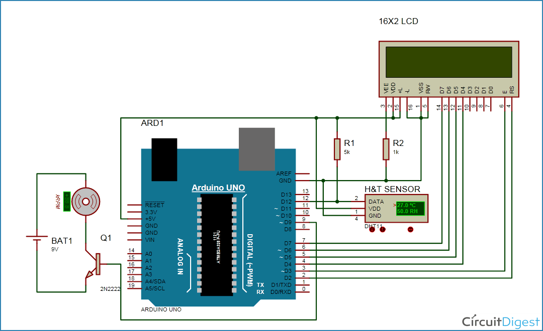
Connections of this temperature controlled fan circuit is very simple, here a liquid crystal display is used for displaying temperature and Fan speed Status. LCD is directly connected to Arduino in 4-bit mode (Check this tutorial for more details: LCD Interfacing with Arduino Uno). Pins of LCD namely RS, EN, D4, D5, D6 and D7 are connected to Arduino digital pin number 7, 6, 5, 4, 3 and 2. And a DHT11 sensor module is also connected to digital pin 12 of Arduino. Digital pin 9 is used for controlling fan speed through the transistor.
If you are looking for something simple and more cost-effective you can check out the temperature controlled LED using LM35 and Temperature controlled Automatic AC switch projects, both of them are very easy to built and does not need a microcontroller.
Arduino Code for temperature-controlled fan
First, we include the library for LCD and DHT sensor and then define pin for lcd, dht sensor and for fan.
Then initialize all the things in setup loop. And in loop by using dht function reads DHT sensor and then using some dht functions we extract temperature and display these on LCD.
After this we compare the temperature with pre define temperature digit and then generate PWM according to the temperature value.
For generating PWM we have used “analogWrite(pin, PWM value)” fuction in 8 bit. Mean if PWM value is equivalent of analog value. So if we need to generate 20% of duty cycle then we pass 255/5 value as PWM in “analogWrite” Function.
Complete Project Code
#include<dht.h>      // Including library for dht
#include<LiquidCrystal.h>
LiquidCrystal lcd(7, 6, 5, 4, 3, 2);
#define dht_dpin 12
dht DHT;
#define pwm 9
byte degree[8] =
              {
                0b00011,
                0b00011,
                0b00000,
                0b00000,
                0b00000,
                0b00000,
                0b00000,
                0b00000
              };
void setup()
{
 lcd.begin(16, 2);
 lcd.createChar(1, degree);
 lcd.clear();
 lcd.print("   Fan Speed  ");
 lcd.setCursor(0,1);
 lcd.print("  Controlling ");
 delay(2000);
 analogWrite(pwm, 255);
 lcd.clear();
 lcd.print("Circuit Digest ");
 delay(2000);
}
void loop()
{
  DHT.read11(dht_dpin);
  int temp=DHT.temperature;
  lcd.setCursor(0,0);
  lcd.print("Temperature:");
  lcd.print(temp);   // Printing temperature on LCD
  lcd.write(1);
  lcd.print("C");
  lcd.setCursor(0,1);
  if(temp <26 )
    {
      analogWrite(9,0);
      lcd.print("Fan OFF            ");
      delay(100);
    }

    else if(temp==26)
    {
      analogWrite(pwm, 51);
      lcd.print("Fan Speed: 20%   ");
      delay(100);
    }

     else if(temp==27)
    {
      analogWrite(pwm, 102);
      lcd.print("Fan Speed: 40%   ");
      delay(100);
    }

     else if(temp==28)
    {
      analogWrite(pwm, 153);
      lcd.print("Fan Speed: 60%   ");
      delay(100);
    }

    else if(temp==29)
    {
      analogWrite(pwm, 204);
      lcd.print("Fan Speed: 80%    ");
      delay(100);
    }
     else if(temp>29)
    {
      analogWrite(pwm, 255);
      lcd.print("Fan Speed: 100%   ");
      delay(100);
    }
  delay(3000);
}
Comments
nice job
Hello, may I ask how much voltage does your DC Fan use. Is it 12 volts?
Could you please fix the code which is in the given above. They are so many errors like dht is not a data type and '.' is not taken before
I just compiled the code and it works fine. What errors did you face?
When posting for an error, make sure you submit enough information about your error for other people to help you.
YOUR GIVEN CODE IS NOT WORKING. SPEED OF FAN IS NOT CHANGING. AND EVEN IF TEMP. IS LESS THAN MIN. TEMP FAN IS NOT STOPING.
IT MEANS BATTERY SUPPY IS DIRECTLY GIVEN TO FAN. THAT'S WHY FAN IS JUST ROTATING WITH SPEED CHANGE.
PLEASE HELP,,,,IF YOU HAVE SOLUTIONS..........
have looked everywhere and tried it a bunch of different ways and just cannot get it to work. have received comments telling to get a better sensor, and all sorts of other suggestions that didn't answer the question. i know how to do it with a 12v fan and a transistor, with the fan having it's own power supply... but i want this as small and simple as possible - has to fit in a beehive - humidity is high, turn on fan. humidity is low, turn off fan. would have thought it was easy, but maybe it's just me! what am i missing?
I tried to repeat this project, but the first time it did not work out due to a library error and an electrical circuit.
Standard library DHT will not work in this project.
From the comment "Alain" I made the changes as he recommended. I also downloaded the dnt11 library (unzip it to the / libraries / folder in the main folder where Arduio IDE is installed)
then correct the circuit for the fan to work properly.
After that, everything worked
I attach a link to the circuit, sketch and library
Hi, does anyone know the maximum temperature can be controlled by the fan? i want to make a chamber that can control the temperature within 33-40 degree celsius. Thank u in advance.
Все работает идеально, как автор говорил не нужно чет там строить велосипед чет менять и переделывать, нужно поставить нормальную библиотеку и все работает, да мучался долго пока нашел ее, я дкмаю переделывать чет еще дольше))), автору респект


After messing around with issues as descibed in the comments I got it working with these libraries and code below. Hope this helps.
Libraries:
DHT_sensor_library 1.3.0
Adafruit_Unified_Sensor 1.0.2
Code:
//**TEMPERATURE CONTROLLED FAN**
//Authored by Saddam of Circuit Digest 03/08/18
//Modified to work with later DHT libraries by Tim Verkerk 27/11/18
#include<DHT.h> // Including library for DHT
#include<DHT_U.h>
#include<LiquidCrystal.h>
LiquidCrystal lcd(7, 6, 5, 4, 3, 2);
#define DHTPIN 12
#define DHTTYPE DHT11
DHT dht(DHTPIN,DHTTYPE);
#define pwm 9
byte degree[8] =
{
0b00011,
0b00011,
0b00000,
0b00000,
0b00000,
0b00000,
0b00000,
0b00000
};
void setup()
{
lcd.begin(16, 2);
lcd.createChar(1, degree);
lcd.clear();
lcd.print(" FAN SPEED ");
lcd.setCursor(0,1);
lcd.print(" CONTROLLER ");
delay(2000);
analogWrite(pwm, 255);
lcd.clear();
lcd.print("STARTING ");
delay(2000);
}
void loop()
{
int temp= dht.readTemperature();
lcd.setCursor(0,0);
lcd.print("Temperature:");
lcd.print(temp); // Printing temperature on LCD
lcd.write(1);
lcd.print("C");
lcd.setCursor(0,1);
if(temp <26 )
{
analogWrite(9,0);
lcd.print("Fan OFF ");
delay(100);
}
else if(temp==26)
{
analogWrite(pwm, 51);
lcd.print("Fan Speed: 20% ");
delay(100);
}
else if(temp==27)
{
analogWrite(pwm, 102);
lcd.print("Fan Speed: 40% ");
delay(100);
}
else if(temp==28)
{
analogWrite(pwm, 153);
lcd.print("Fan Speed: 60% ");
delay(100);
}
else if(temp==29)
{
analogWrite(pwm, 204);
lcd.print("Fan Speed: 80% ");
delay(100);
}
else if(temp>29)
{
analogWrite(pwm, 255);
lcd.print("Fan Speed: 100% ");
delay(100);
}
delay(3000);
}