
Today we are building a simple yet very useful circuit using Temperature Sensor LM35. In this circuit, we are going to control the LEDs according to temperature around. If temperature goes beyond a particular level (50 Degree in this circuit) then Red LED will glow automatically, otherwise yellow LED remains on below that particular temperature. This threshold temperature value can be set by adjusting the Variable resistor in the circuit, according to requirement.
This Temperature controlled Lights circuit can be useful in many ways, like it can work as temperature indicator or it can trigger any device like fan or alarm beyond a particular temperature. It can also work as fire alarm if you set the threshold temperature very high like 100 Degree Celsius. In this circuit you will also learn about how to use LM35 sensor in any circuit. LM35 is very popular and inexpensive temperature sensor generally used as digital thermometer or to measure temperature.
Required Components:
- 9v Battery
- IC 7805
- Temperature sensor LM35
- Op-amp LM358
- 10k ohm Resistor (3)
- 1k ohm Resistor (3)
- Variable Resistor 10k
- LEDs (Red and Yellow)
- NPN Transistor BC547 (2)
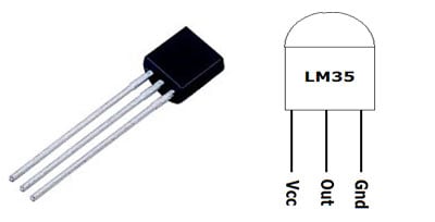
Temperature Sensor LM35:
LM35 is three pin transistor like device. It has VCC, GND and OUTPUT. This sensor provides variable voltage at the output based on temperature. “LM35” provides output in degree Celsius and can sense up to 150 degree Celsius temperature.
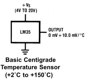
For every +1 centigrade rise in temperature there will be +10mV higher voltage at the output pin. So if the temperature is 0◦ centigrade the output of sensor will be 0V, if the temperature is 10◦ centigrade the output of sensor will be +100mV, if the temperature is 25◦ centigrade the output of sensor will be +250mV.
Setting up Reference Voltage for Op-amp LM358:
Here we have used Op-amp LM358 to compare the output voltage of LM35 with the reference voltage. As mentioned we have set the circuit for threshold voltage 50 Degree, so to trigger the op-amp at 50 Degree, we need to set the reference voltage to 0.5 volt, as at 50 degree temperature LM35 output voltage will be 0.5 volt or 500mV. Reference voltage is the voltage at Pin no 2 of LM358 (seen circuit diagram below).
Now to set the reference voltage, we have created a Voltage Divider circuit by using resistor R1 and Variable resistor RV1 of 10k. By using the above formulae you can set the reference voltage accordingly and can change the Threshold Temperature. Like to set the 50 degree Celsius temperature as triggering value, you can set the potentiometer roughly at 8k:2k like:
Vout = (R2 / R1 + R2) * Vin
(here R2 is second part of potentiometer: 2k ohm and R1 is R1 + first part of potentiometer: 10k+8k)
Vout = (2 / 18 + 2) * 5 = 0.5v
Op-amp LM358:
Op-amps are also known as Voltage Comparators. When voltage at non-inverting input (+) is higher than the voltage at inverting input (-), then the output of comparator is High. And if the voltage of inverting input (-) is Higher than non-inverting end (+), then output is LOW. Know more about working of op-amp here.
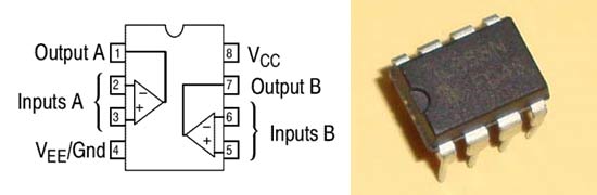
LM358 is a Dual Low Noise Operational Amplifier which has two independent voltage comparators inside. This is a general purpose op amp which can be configured in many modes like comparator, summer, integrator, amplifier, differentiator, inverting mode, non- inverting mode, etc.
Circuit Diagram:

Working Explanation:
Working of this Temperature Controlled Lights Project is simple. 9v general purpose battery is used to power up the whole circuit and IC7805 is used to provide the regulated 5v supply to the circuit. When temperature is below 50 degree Celsius then yellow LED remains ON and RED remains OFF. When temperature is below 50 degree then output of LM358 remains LOW and Q1 remains in OFF state and transistor Q2 remains in ON state.
Now when surrounding’s temperature goes beyond 50 Degree Celsius, output voltage of LM35 at pin 2 also goes higher than 0.5 volt or 500mV. Output of LM35 is connected to Pin 3 of Op-amp LM358. And as we have set the reference voltage (voltage at Pin 2 of LM358) to 0.5 volt, so now voltage at Pin 3 (non-inverting input) becomes higher than voltage at Pin 2 (inverting input) and output of opamp LM358 (PIN 1) becomes HIGH. Output of LM358 connected to the base of NPN transistor Q1, so Q1 also becomes ON and Red LED starts glowing. At the same time, base of Transistor Q2 gets ground and Q2 becomes OFF and yellow LED also becomes OFF. So that’s how the circuit detects the temperature limit and indicates by glowing the Red LED.
In the demonstration video below, we have used soldering iron to heat up the surrounding near Temperature sensor LM35, check it.
Comments
Simple project
We connect the same circuit but we didn't get output only yellow LED is glowing but red Led is not glow when apply heating to LM35 can you please suggest the circuit for which you have got output
Can i use 2904D JRC IC in this circuit? I replaced LM358 and used 2904D but the problem is , the red LED was the one lighting . And when I try to heat LM35 , the red LED was still on . Can someone help me? What IC can i use to make this project work properly? Thanks
can you suggest me how to built a temperature senser for refrigerator which should work on 48v dc.
What happens when the temperature is exactly 50 degrees Celsius? Will both LEDs turn on? Thank you.
- Can you tell me, what I need if I don't want 9V but 12V in my PC? Is R, RV, Q changing? (anything else?)
- Is it possible to light D2 at 40°C an D1 at 60°C and nothing up to 40°C?
- Can I start a pc-fan with D2 an D1 with different V? For example D2 at 40°C together with the fan in low V an D1 at 60°C with the fan in maximum V (10-12V)?
I don't use L7805 ic yet I find successfully result.
This project is simple but how we increase it's range?
Can i put relay if the temperature goes beyond 50 Degree Celsius?
yes you can, make sure you use a relay driver circuit or use a module to keep it simple
Is it possible to replace the heating LED with a DC powered fan??
LEDs don't heat, they glow.
Yes, you can use a fan in place of LED provided its a small fan which consumes less than 200mA
lol ofcourse i was meaning in place of the led representing the heating aspect. But cool thanks! about to try it out
The only light that is coming on is the heating light and automatically when the battery source is applied. I troubleshooted for a minute and realized that I needed to adjust my variable resistor it then became yellow and worked. This worked for a couple of seconds and wouldn't go back Yellow. Any suggestions?
The only light that is coming on is the heating light and automatically when the battery source is applied. I troubleshooted for a minute and realized that I needed to adjust my variable resistor it then became yellow and worked. This worked for a couple of seconds and wouldn't go back Yellow. Any suggestions?
What if there were to be 3 LEDs instead of 2?
What do you need the 3rd LED to do?
I would like to have a range of temperatures, so if the temperature goes higher than 25 ºC then one LED flashes, if the temperature is somewhere between 15-25 ºC another one flashes,and finally if the temeprature is lower than 15 ºC a third LED flashes. Although temperatures would not have to be as exact.
I used the very same circuit but only the yellow led is corresponding what should I fix ?

Very helpful&educating