Proximity sensing is a common application for intruder alarms, light switches, and other home and industrial automation applications. There are multiple methods of proximity detection used in the electronics industry. The most common method is to use the PIR sensor, which senses the change in ambient infrared radiation caused by a warm body. And other common methods involve using reflected ultrasonic or light beams, in which the intruding object reflects the beam back to its source where the time delay between transmission and reception is measured to calculate the distance to the object.
In this tutorial, we are going to look at another method of proximity detection using microwaves and the Doppler Effect. As advanced as this sounds, it can be accomplished easily using a cheap sensor called the RCWL-0516.
RCWL 0516 Module

The RCWL-0516 Microwave Radar Sensor module has been designed as an alternative to the common PIR motion sensors widely used in burglar alarms and security lights. Like the PIR Sensor, this sensor also detects only movements within its detection range. But instead of sniffing the blackbody radiation from a moving person, this sensor uses a “microwave Doppler radar” technique to detect moving objects.
The module has the characteristics of high sensitivity, high induction distance, high reliability, large induction angle, wide power supply voltage range, etc. It is widely used in various kinds of human body induction lighting and alarm and so on. This module supports wide input voltage, ranging from 4 to 28V DC, and is equipped with RCWL-9196 chip RCWL with very minimal data available on the internet. It has a sensitivity range of ~7 meters. When triggered, its TTL-level output (OUT) pin will switch from LOW (0 V) to HIGH (3.3 V) for a finite time (2 to 3 s) before returning to its idle (LOW) state.
Specifications:
- Supply Voltage: 4–28 VDC
- Operating frequency: ~3.2 GHz
- Transmit power: 20 mW (typical)/30 mW (max)
- Sensing Distance: 5–7 m
RCWL 0516 Module Pinout
The RCWL0516 module has a total of 5 pins. In which at least 4 pins are necessary for the interfacing. The pinout of the module is as follows:

VCC - Provides power for the module, Connect to the 5V pin of the Arduino.
GND - Ground Connected to Ground pin of the Arduino.
SCL – Module output (HIGH (3.3 V) motion detected/LOW (0 V) idle).
CDS – Sensor disable input (low = disable). This pin is directly connected to the enable pin of the RCWL-0516 chip.
3.3V – 3.3V regulated output. Max 100mA.
RCWL 0516 Module Parts
The RCWL 0516 module consists of an ASIC chip RCWL9196 from RCWL. The RCWL9196 comes in a 16-pin SOIC package. The module contains all the complimentary components along with a single transistor-based high-frequency oscillator which generates the microwave signal with a frequency of around 3.175GHz, with a wavelength of 9.45cm and half wavelength of 4.725cm. There is also a power led which indicates the power status of the module.

The below image from the datasheet shows the frequency characteristics of the module.

The below image shows the internal structure of the RCWL9196 chip along with the mode pin characteristics and the decapsulated image of the same chip.

RCWL 0516 Module Circuit Diagram
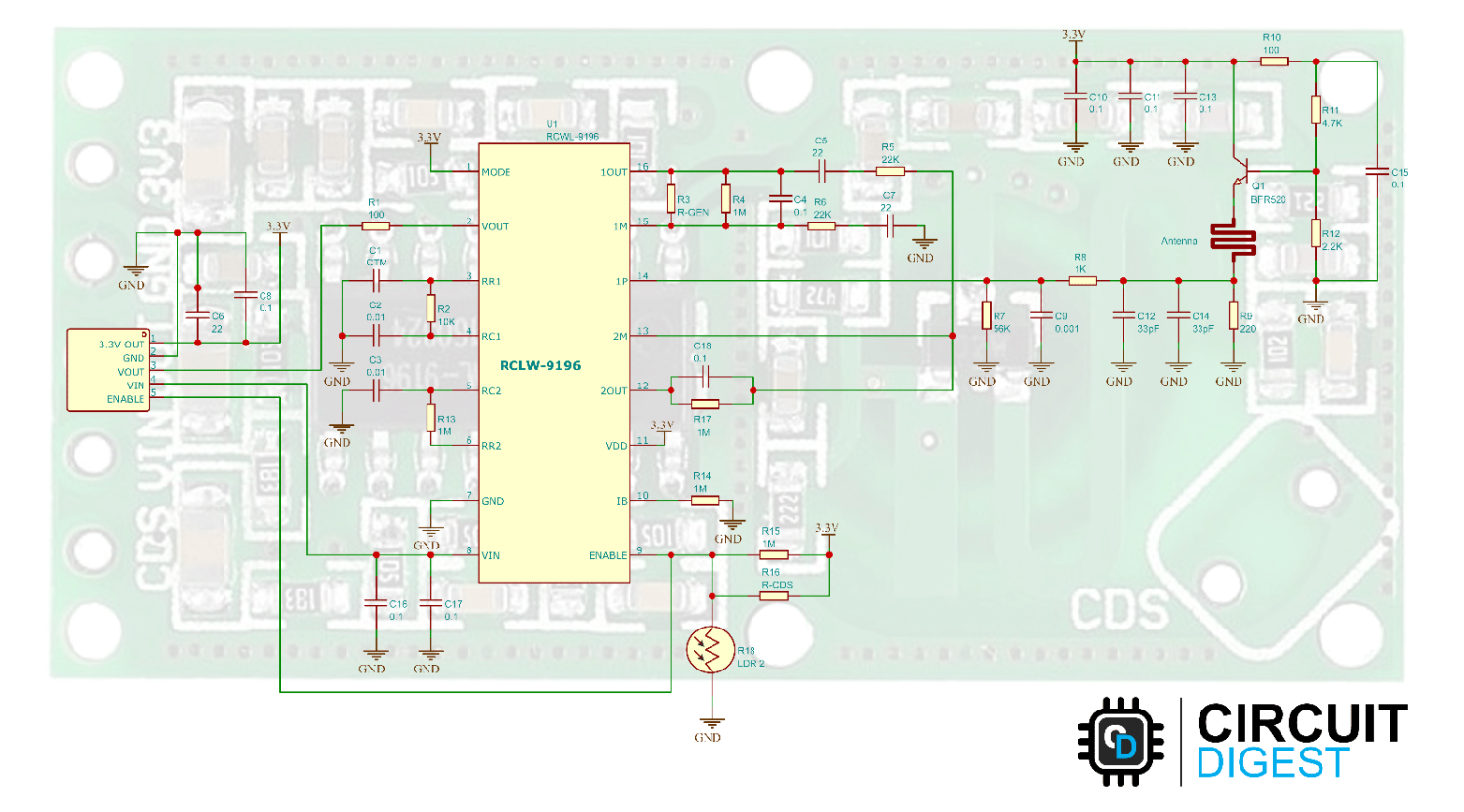
The schematic diagram from the RCWL0516 module is given below. As mentioned earlier the main component on board is the RCWL-9196 chip. The 3.3V output is directly taken from the VDD pin of the chip.
The PCB trace antenna act as an inductor. This inductor along with the parasitic capacitance and the transistor forms a cockpit oscillator and creates a microwave signal with a frequency of 3.175Ghz.
Commonly Asked Questions
Q. How does a microwave motion sensor work?
Doppler microwave detection devices transmit a continuous signal of low-energy microwave radiation at a target area and then analyze the reflected signal. The detector registers a change in the frequency of waves occurring when the microwave source and the target are in motion relative to one another.
Q. How do you block a motion sensor in a microwave?
Covering a motion sensor is effective in blocking it if the material doesn't let the waves pass through. Aluminum foils are helpful against microwave motion sensors.
Q. What are the advantages of microwave motion sensors?
Microwave sensor waves are able to go through walls and holes which allows them to have a wide detection range. This allows them to cover large areas and also large outdoor areas.
Arduino RCWL 0516 RADAR Sensor Module Circuit Diagram
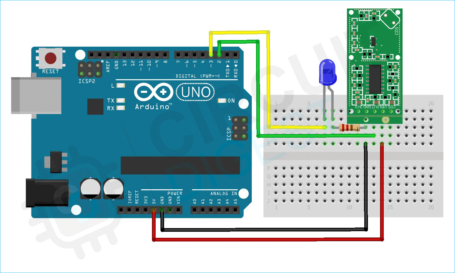
The following image shows the circuit diagram for interfacing the RCWL0516 module with Arduino. The RCWL0516 uses just one pin to indicate motion detection. Connect the VIN and GND to the 5V and GND pins of the Arduino. Connect the VOUT pin to the D2 pin of the Arduino. Also, connect the LED to pin D3 and GND through a current limit resistor.
Here is how the real-life connection looks.

Arduino Code for Interfacing RCWL 0516 Module
In this example, we are going to turn on and off the LED with the help of proximity detection. The LED will turn on when proximity is detected and will turn off after 2 seconds when there is no proximity.
Code Explanation
The program is pretty simple. In the starting, we have defined the sensor pin and the LED output pin. And in the setup function, we have initialized these pins as input and output.
int Sensor = 2;     // RCWL-0516 Input Pin
int LED = 3;       // LED Output Pin
void setup() {
  pinMode (Sensor, INPUT);  // RCWL-0516 as input
  pinMode (LED, OUTPUT);    // LED as OUTPUT
  digitalWrite(LED, LOW);   // Turn LED Off
}
In the loop function, we will monitor the sensor pin all the time and when the sensor pin goes HIGH, that means a proximity change is detected, and the microcontroller will turn on the light. The light will stay on until the sensor pin goes low. By default, the Bout pin of the module will stay on for 2 Seconds when a motion is detected. After that, it will go LOW and wait for the next trigger. We can change the trigger time by populating the CTM capacitor on board.
void loop() {
  Bool SensValue = digitalRead(Sensor);  // Read Sensor value
  if (sensorval == HIGH) {
    digitalWrite(LED, HIGH);  // Turn LED On
  }
  else {
    digitalWrite(LED, LOW);  // Turn LED Off
  }
}
RCWL 0516 Interfacing with Arduino
The below GIF shows how we have interfaced an RCWL0516 module with the Arduino. As you can see as soon as I wave my hand the module triggers and the LED turns on for two seconds.
Supporting Files
Complete Project Code
int Sensor = 2;     // RCWL-0516 Input Pin
int LED = 3;       // LED Output Pin
void setup() {
  pinMode (Sensor, INPUT);  // RCWL-0516 as input
  pinMode (LED, OUTPUT);    // LED as OUTPUT
  digitalWrite(LED, LOW);   // Turn LED Off
}
void loop() {
  Bool SensValue = digitalRead(Sensor);  // Read Sensor value
  if (sensorval == HIGH) {
    digitalWrite(LED, HIGH);  // Turn LED On
  }
  else {
    digitalWrite(LED, LOW);  // Turn LED Off
  }
}
}


