
In this project we are going to make a Buck Converter Circuit using Arduino and N-Channel MOSFET with a maximum current capacity of 6 amps. We are going to step down 12v DC to any value between 0 and 10v DC. We can control the output voltage value by rotating the potentiometer.
A buck converter is a DC to DC converter, which steps down DC voltage. It is just like a transformer with one difference; whereas transformer steps down AC voltage buck converter steps down DC voltage. Efficiency of buck converter is lower than a transformer.
Key components of buck converter are mosfet; either n-channel or p-channel and high frequency Square Pulse Generator (either a timer IC or microcontroller). Arduino is used here as Pulse Generator, a 555 Timer IC can also be used for this purpose. Here we have demonstrated this Buck converter by controlling DC-Motor speed with Potentiometer, also tested the voltage using Multimeter. Check the Video at the end of this article.
Required Components:
- Arduino Uno
- IRF540N
- Inductor(100Uh)
- Capacitor (100uf)
- Schottky Diode
- Potentiometer
- 10k, 100ohm Resistor
- Load
- 12v Battery
Circuit Diagram and Connections:

Make connections as shown in circuit diagram above for DC-DC Buck Converter.
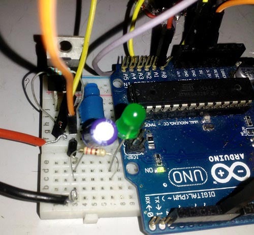
- Connect one terminal of inductor to source of mosfet, and another to LED in series with 1k resistor. Load is connected in parallel to this arrangement.
- Connect 10k resistor between gate and source.
- Connect capacitor in parallel to load.
- Connect positive terminal of battery to drain and negative to capacitor’s negative terminal.
- Connect p terminal of diode to negative of battery and n terminal directly to source.
- PWM pin of Arduino goes to gate of mosfet
- GND pin of Arduino goes to source of mosfet. Do connect it there or circuit will not work.
- Connect potentiometer’s extreme terminals to 5v pin and GND pin of Arduino respectively. Whereas wiper terminal to analog pin A1.
Function of Arduino:
As already explained, Arduino sends clock pulses to base of MOSFET. Frequency of these clock pulses is approx. 65 Khz. This causes very fast switching of mosfet and we obtain an average voltage value. You should learn about ADC and PWM in Arduino, which will clear you how high frequency pulses are generated by Arduino:
Function of MOSFET:
Mosfet is used for two purposes:
- For high speed switching of the output voltage.
- To provide high current with less dissipation of heat.
Function of inductor:
Inductor is used to control voltage spikes which can damage mosfet. Inductor stores energy when mosfet is on and releases this stored energy when mosfet is off. Since frequency is very high, value of inductance required for this purpose is very low (around 100uH).
Function of Schottky Diode:
Schottky diode completes the loop of current when mosfet is switched off and thus ensuring smooth supply of current to load. Apart from this, schottky diode dissipates very low heat and work fine at higher frequency than regular diodes.
Function of LED:
Brightness of LED indicates the step down voltage across load. As we rotate the Potentiometer, brightness of LED varies.
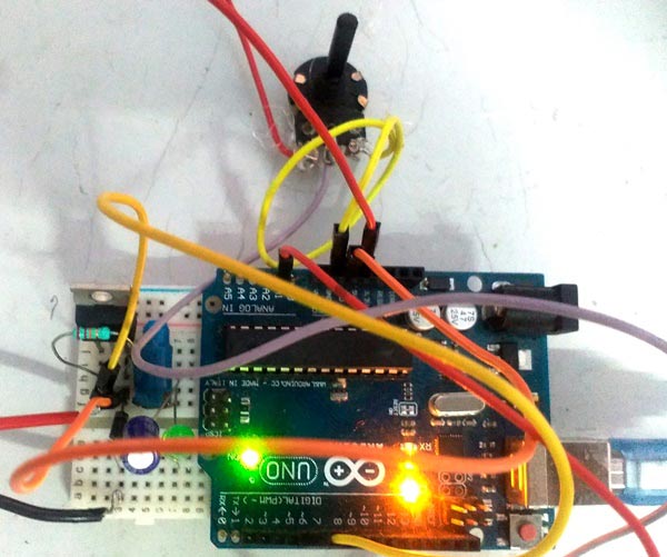
Function of potentiometer:
When wiper terminal of potentiometer is thrown off to different position, voltage between it and ground changes which in turn changes the analog value received by pin A1 of arduino. This new value is then mapped between 0 and 255 and then given to pin 6 of Arduino for PWM.
** Capacitor smooths out voltage given to load.
Why resistor between gate and source?
Even slightest noise at gate of MOSFET can turn it on, hence to prevent this from happening it is always advised to connect high value resistor between gate and source.
Code Explanation:
Complete Arduino code, for generating high frequency pulses, is given in the code section below.
Code is simple and self-explanatory, so here we have explained only few parts of code.
Variable x is assigned the analog value that is received from analog pin A0 of Arduino
x= analogRead(A1) ;
Variable w is assigned the mapped value which is between 0 and 255. Here the ADC values of Arduino are mapped to 2 to 255 using map function in Arduino.
w= map(x,0,1023,0,255) ;
Normal frequency of PWM for pin 6 is approx.1khz. This frequency is not suitable for purposes like buck converter. Hence this frequency must be increased to a very high level. This can be achieved using a one line code in void setup:
TCCR0B = TCCR0B & B11111000 | B00000001;// change frequency of pwm to 65 KHZ approx.
Working of DC-DC Buck Converter:
When circuit is switched on, mosfet switches on and off with a frequency of 65 khz. This causes inductor to store energy when mosfet is on and then give this stored energy to load when mosfet switches off. Since this happens at very high frequency, we get an average value of pulsed output voltage depending on the position of wiper terminal of potentiometer with respect to 5v terminal. And as this voltage between wiper terminal and ground increases so does the mapped value on pwm pin no. 6 of Arduino.
Let’s say this mapped value is 200. Then PWM voltage on pin 6 will be at:

[ (200*5) / 255 ]= 3.921 volts
And since MOSFET is a voltage dependent device, this pwm voltage ultimately determines the voltage across load.
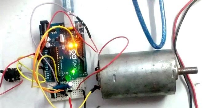
Here we have demonstrated this Buck converter by rotating a DC-Motor and on Multimeter, check the Video below. We have controlled the speed of motor with Potentiometer and controlled the brightness of LED with Potentiometer.
Complete Project Code
int x; // initialize variables

int w;
void setup() {

  pinMode(6,OUTPUT);// pwm pin 6 as output pin

  pinMode(A1,INPUT);// analog pin as input

  TCCR0B = TCCR0B & B11111000 | B00000001;// change frequency of pwm to 65 KHZ approx( explained under code section)

  Serial.begin(9600);// begin serial communication

 }
void loop() {

  x= analogRead(A1);

  w= map(x,0,1023,0,255);

  analogWrite(6,w); // write mapped value on pin 6

  Serial.print("w    "); //print mapped value on screen

  Serial.println(w);

 }
Comments
If I want to convert 24 v dc to lower DC voltage what should I do?
There are a lot of possibilities based on your current requirement
I want duty cycle and output voltage to show at 16x2 lcd .. what will be the changes in the code .. can anyone plz tell .. ihave to submit this project upcomming wednesday
Can u add a feedback to the code so that the output voltage become stable with changing load?
i want generate gate pulses for my boost converter which has 2 switches s1 and s2 with duty cycles 76 and 36.the switching frequency is 100khz.. how to write a code for that
i want to build a boost converter using a similar set up how can i modify the code to boost the converter
I m sorry but this is not dc-dc converter is driver with pwm.

It's very good