

Are you tired of having shaky footage ruin your video? Or do you want to make some cinematic, professional-looking shots? Let’s make a cheap and easy-to-make camera slider to solve these problems. In this project, we are going to make a motorized camera slider using Arduino. The entire system is made using off-the-shelf parts such as stepper motors, motor drivers, and Arduinos and it is designed to be very versatile. If you are looking something more simple with only pan and tilt and no slider, you can check out this Arduino Face Tracking Robot Project.
How will our DIY Camera Slider Work?
The working of the Camera Slider is pretty simple. We will use two stepper motors for each axis of movement. A limit switch is used to detect the homing position. As soon as the device is powered on the Arduino will activate the Linear axis motor and it will be active until the limit switch is activated. Once the platform is reached the homing position, ie the limit switch is activated the Arduino will set this position as the home position or the Zero position for the linear axis. After that, the Arduino will walk us through the steps in which we can set the Slide in, Slide out, Pan in, and Pan out positions along with the movement speed. The entire menu is controlled using a single EC11 rotary encoder. Once all the setup is complete you can start the movement by the start option, or you can restart the process by selecting the cancel button if necessary. The below GIF shows our Arduino motorized Slider in Action, it looks pretty cool, right? So keep reading and I will explain every detail to build this DIY motorized camera slider with pan and tilt head which you can use with your smartphone camera or professional DSLR camera.
Complete code and detailed video for this Stepper Motor Camera Slider using Arduino is given at the end.
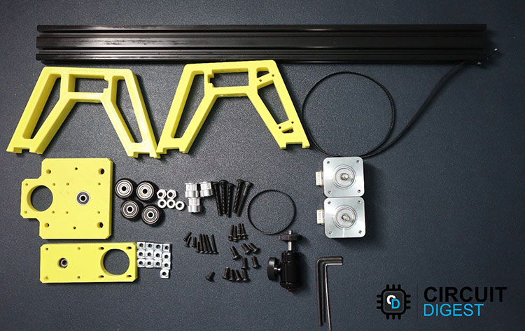
Components Required to Build Arduino Camera Slider
All the parts you will require to build the camera slider are listed below. For the motor driver, you can use either A4988 or DRV8825 or the TMC2209. All of them would work with a little modification in the code while providing more stepping accuracy of 16, 32 and 128 in the given order. In the below project, we have used the TMC2209 V1.2 from BigTreeTech.
- Arduino Nano – 1
- Motor Driver (A4988/DRV8825/ TMC2209) – 2
- OLED display 128x64 – 1
- Rotary encoder module HW-040 - 1
- NEMA N17 Stepper motor – 2
- Limit Switch 3 Pin SPDT – 2
- On /Off Switch – 1
- DC socket 5521 - 1
- Aluminium Profile 2040 V slot – 50cm
- M5 Aluminium spacer 5mm bore 6mm length – 3
- M5 Aluminium Eccentric spacer 5mm bore 6mm length – 2
- M3 Button head bolt 20mm – 16
- M3 Button head bolt 10mm – 4
- M3 Allen key head bolt 20mm – 4
- M5 Button head/ Flat/ Philips bolt 15 mm – 10
- M5 Button head bolt 35 mm – 4
- M5 Button Head bolt 50mm – 1
- M3 Lock nut - 8
- M5 lock nut - 5
- M5 Sliding T nut – 10
- Derlin POV V-wheel 625RS – 4
- GT2 Timing pully 20 Teeth 5mm bore for 6mm belt – 3
- GT2 timing belt open loop 6mm width – 100cm
- GT2 Timing belt closed loop 6 mm width – 158mm
- 625RS bearing – 2
- Camera Ball mount -1
- Wires
- Cable sleeve
- Connectors and pin headers
- Pref board
- Cable tie
- 3D printed parts
- Other necessary tools
3D Printed Parts for Arduino Camera Slider
The files for all the 3D printed parts for this motorized slider using arduino can be downloaded from the GitHub link provided at the end of the article along with the Arduino sketch and bitmap file. It is recommended to print the parts with higher infill for better quality and sturdiness. To learn more about 3D printing basics, please follow the link.
Camera Slider Circuit Diagram
The complete circuit diagram for the Arduino based DIY Camera slider is shown below.

The schematic diagram for the camera slider is very simple. The OLED is connected to the A4 and A5 pins of the Arduino along with the 5V and GND pins. The rotary encoder’s SW pin is connected to the D2, while CLK is connected to the D3, and the DT pin is connected to the D4. VCC and GND are connected to the 5V and GND pins respectively. The end switches are connected to the D9 and D10. At the moment we only use one end-stop switch. The other can be used if you want to change the home passion to the other end.
The connections to the motor driver are identical. 12V supply is connected to the VMOT pins of the drivers and the VIN pin of the Arduino through an ON/OFF switch. RST and SLP pins are connected to each other. The MS1, and MS2 pins are tied to the 5V line, while enable pin in connected to ground. All the ground pins are connected together while A1, A2, B1, and B2 pins are connected to the respective stepper motor. An electrolytic capacitor with a value of minimum 100uF is connected to the VMOT and GND pins in order to protect the motor drivers as well as the Arduino from any potential back EMF from the stepper motor.
Arduino Code for the DIY Camera Slider
As a first step make sure to install the Adafruit GFX, Adafruit SSD1306, and AccelStepper libraries from the library manager. These libraries are necessary to compile the code. Also, make sure to put the bitmap.h file to the sketch folder This file contains all the icons and images we are going to use to display in the OLED display. And the below code is specifically written for TMC2209 V1.2 from BigTreeTech. If you choose another type of motor driver , you may need to change the specific values such as maxspeed and stepsPerRevolution. Now let’s look at the code.
#include <Wire.h>
#include <Adafruit_GFX.h>
#include <Adafruit_SSD1306.h>
#include <AccelStepper.h>
#include <MultiStepper.h>
#include "bitmap.h"
At the start, we included all the necessary libraries. The wire library is used along with the Adafruit_GFX and Adafruit_SSD1306 to control the OLED display. Detailed article on interfacing OLED with Arduino can be found here. Also check other OLED based projects here.
AccelStepper library is used to control the stepper motors. Multistepper.h header file is also a part of AccelStepper library. As mentioned earlier bitmap.h file contains all the bitmap information. Learn more about stepper motor & its working and stepper motor interfacing with Arduino by following the links.
#define SCREEN_WIDTH 128  // OLED display width, in pixels
#define SCREEN_HEIGHT 64  // OLED display height, in pixels
#define I2Cspeed 1000000
#define limitSwitch 10
#define PinSW 2
#define PinCLK 3
#define PinDT 4
#define OLED_RESET -1
#define SCREEN_ADDRESS 0x3C
Adafruit_SSD1306 display(SCREEN_WIDTH, SCREEN_HEIGHT, &Wire, OLED_RESET);
AccelStepper stepper2(1, 8, 7);  // (Type:driver, STEP, DIR)
AccelStepper stepper1(1, 6, 5);
MultiStepper StepperControl;
long gotoposition[2];
int selection;
volatile long XInPoint = 0;
volatile long YInPoint = 0;
volatile long XOutPoint = 0;
volatile long YOutPoint = 0;
volatile long totaldistance = 0;
int flag = 0;
int temp = 0;
int i, j;
unsigned long switch0 = 0;
unsigned long rotary0 = 0;
float setspeed = 200;
float motorspeed;
float timeinsec;
float timeinmins;
volatile boolean TurnDetected;
volatile boolean rotationdirection;
const int stepsPerRevolution =200;
const int maxspeed = 6000;
Then we defined variables such as screen resolutions, I2C speed, display I2C address and the connections to the rotary encoder. After that, we created the instances for the display and two stepper motors. All the global variables are also declared.
void oledDisplayCenter(const char* text, int x, int y) {
  int16_t x1;
  int16_t y1;
  uint16_t width;
  uint16_t height;
  display.getTextBounds(text, x, y, &x1, &y1, &width, &height);
  display.setCursor((SCREEN_WIDTH - width) / 2, y);
  display.print(text);  // text to display
}
OledDisplayCentre function is used to centre the text on the display. This function will get the text length and calculate the text width. After that, the cursor is set to the appropriate passion so that the text will be centred with respect to the X axis.
void Switch() {
  if (flag == 7 && selection == 0 && millis() - switch0 > 500)
  {
    flag = 10;
  }
  else if (millis() - switch0 > 500) {
    flag = flag + 1;
    selection = 1;
  }
  switch0 = millis();
}
The Switch function handles all the button clicks of the rotary encoder. This function will handle the screen change and setup process. This function is attached to the hardware interrupt. And as soon as an interrupt is happed, ie the switch is pressed this function will execute.
void Rotary() {
  delay(75);
  if (digitalRead(PinCLK))
    rotationdirection = digitalRead(PinDT);
  else
    rotationdirection = !digitalRead(PinDT);
  TurnDetected = true;
  delay(75);
}
The Rotary function will execute as soon as an interrupt occurs at the D3 pin, which is connected to the CLK pin of the rotary encoder. When this function is executed, it will detect the rotation direction and will set the rotationdirection flag accordingly. It will also set another flag called TurnDetected to let the loop function know that a turn is detected.
void setup() {
  Serial.begin(9600);
  stepper1.setMaxSpeed(3000);
  stepper1.setSpeed(200);
  stepper2.setMaxSpeed(3000);
  stepper2.setSpeed(200);
  pinMode(limitSwitch, INPUT_PULLUP);
  pinMode(PinSW, INPUT_PULLUP);
  pinMode(PinCLK, INPUT_PULLUP);
  pinMode(PinDT, INPUT_PULLUP);
  display.begin(SSD1306_SWITCHCAPVCC, 0x3C);
  display.clearDisplay();
  // Create instances for MultiStepper - Adding the 2 steppers to the StepperControl instance for multi control
  StepperControl.addStepper(stepper1);
  StepperControl.addStepper(stepper2);
  attachInterrupt(digitalPinToInterrupt(PinSW), Switch, RISING);  // SW connected to D2
  attachInterrupt(digitalPinToInterrupt(PinCLK), Rotary, RISING);  // CLK Connected to D3
  // display Boot logo
  for (int i = 124; i > 0; i = i - 4) {
    display.drawBitmap(i, 0, CamSlider, 128, 64, 1);
    display.display();
    display.clearDisplay();
  }
  delay(1000);
  display.clearDisplay();
  Home();  // Move the slider to the initial position - homing
}
In the setup function first, we initialised the serial communication with a baud rate of 9600 for debug purposes. Later we initialised the stepper driver. We also set all the input pins as input and initialised the OLED library too. Then created a multistepper instance to control the two stepper motors. Then attached the Switch and Rotary functions to the respective pins using attachInterrupt. After that, A small boot animation is displayed. Then the Home function is called.
void Home() {
  stepper1.setMaxSpeed(3000);
  stepper1.setSpeed(200);
  stepper2.setMaxSpeed(3000);
  stepper2.setSpeed(200);
  if (digitalRead(limitSwitch) == 1) {
    for (int i = 92; i > 3; i = i - 4) {
      display.drawBitmap(17, 5, Homing, 92, 27, 1);
      display.drawBitmap(0, 51, slider, 128, 13, 1);
      display.drawBitmap(i, 40, camera, 20, 17, 1);
      display.display();
      display.clearDisplay();
    }
  }
  while (digitalRead(limitSwitch) == 1) {
    stepper1.setSpeed(-3000);
    stepper1.runSpeed();
  }
  delay(20);
  stepper1.setCurrentPosition(0);
  stepper1.moveTo(200);
  while (stepper1.distanceToGo() != 0) {
    stepper1.setSpeed(3000);
    stepper1.runSpeed();
  }
  stepper1.setCurrentPosition(0);
  display.clearDisplay();
}
The Home function will monitor the end-stop switch and move the linear axis motor to the Home position till the end stop switch is activated. Once the carriage is in home position the Arduino will record this as the Home position or the Zero position. Every linear axis motor movement after this will be with respect to this position.
void SetSpeed() {
  display.clearDisplay();
  while (flag == 6) {
    if (TurnDetected) {
      TurnDetected = false;  // do NOT repeat IF loop until new rotation detected
      if (rotationdirection) {
        setspeed = setspeed + 30;
      }
      if (!rotationdirection) {
        setspeed = setspeed - 30;
        if (setspeed < 0) {
          setspeed = 0;
        }
      }
      display.clearDisplay();
      display.setTextSize(2);
      display.setTextColor(WHITE);
      display.setCursor(30, 0);
      display.print("Speed");
      motorspeed = setspeed / 80;
      display.setCursor(5, 16);
      display.print(motorspeed);
      display.print(" mm/s");
      totaldistance = XOutPoint - XInPoint;
      if (totaldistance < 0) {
        totaldistance = totaldistance * (-1);
      }
      timeinsec = (totaldistance / setspeed);
      timeinmins = timeinsec / 60;
      display.setCursor(35, 32);
      display.print("Time");
      display.setCursor(8, 48);
      if (timeinmins > 1) {
        display.print(timeinmins);
        display.print(" min");
      } else {
        display.print(timeinsec);
        display.print(" sec");
      }
      display.display();
    }
    display.clearDisplay();
    display.setTextSize(2);
    display.setTextColor(WHITE);
    display.setCursor(30, 0);
    display.print("Speed");
    motorspeed = setspeed / 80;
    display.setCursor(5, 16);
    display.print(motorspeed);
    display.print(" mm/s");
    totaldistance = XOutPoint - XInPoint;
    if (totaldistance < 0) {
      totaldistance = totaldistance * (-1);
    }
    timeinsec = (totaldistance / setspeed);
    timeinmins = timeinsec / 60;
    display.setCursor(35, 32);
    display.print("Time");
    display.setCursor(8, 48);
    if (timeinmins > 1) {
      display.print(timeinmins);
      display.print(" min");
    } else {
      display.print(timeinsec);
      display.print(" sec");
    }
    display.display();
  }
}
The Setspeed function will calculate and record the movement speed when we set it in the loop function. This function will also calculate and display the Speed and time to the OLED too.
void select() {
  if (TurnDetected)
  {
    TurnDetected = false;
    if (rotationdirection && selection == 0)
    {
      selection = 1;
      Serial.print("selection: ");
      Serial.println(selection);
    }
    if (!rotationdirection && selection == 1)
    {
      selection = 0;
      Serial.print("selection: ");
      Serial.println(selection);
    }
  }
}
The select function is called after the setup procedure is complete. During this we can decide to start the slide we set or we can reset and start over. The display will show two icons, one for the start function and another one for cancel. The user can select the appropriate one and press the encoder to confirm.
void stepperposition(int n) {
  stepper1.setMaxSpeed(maxspeed);
  stepper1.setSpeed(stepsPerRevolution);
  stepper2.setMaxSpeed(maxspeed);
  stepper2.setSpeed(stepsPerRevolution);
  if (TurnDetected) {
    TurnDetected = false;  // do NOT repeat IF loop until new rotation detected
    if (n == 1) {
      if (!rotationdirection) {
        if (stepper1.currentPosition() - 200 > 0) {
          stepper1.move(-200);
          while (stepper1.distanceToGo() != 0) {
            stepper1.setSpeed(-maxspeed/2);
            stepper1.runSpeed();
          }
        } else {
          while (stepper1.currentPosition() != 0) {
            stepper1.setSpeed(-maxspeed/2);
            stepper1.runSpeed();
          }
        }
      }
      if (rotationdirection) {
        if (stepper1.currentPosition() + 200 < 149000) {
          stepper1.move(200);
          while (stepper1.distanceToGo() != 0) {
            stepper1.setSpeed(maxspeed/2);
            stepper1.runSpeed();
          }
        } else {
          while (stepper1.currentPosition() != 149000) {
            stepper1.setSpeed(maxspeed/2);
            stepper1.runSpeed();
          }
        }
      }
    }
    if (n == 2) {
      if (rotationdirection) {
        stepper2.move(-10);
        while (stepper2.distanceToGo() != 0) {
          stepper2.setSpeed(-maxspeed);
          stepper2.runSpeed();
        }
      }
      if (!rotationdirection) {
        stepper2.move(10);
        while (stepper2.distanceToGo() != 0) {
          stepper2.setSpeed(maxspeed);
          stepper2.runSpeed();
        }
      }
    }
  }
}
The stepperposition function will control the motors and move the carriage or head during the setup procedure. This function will move the motor according to the rotary encoder movement during the process.
void loop() {
  //Begin Setup
  if (flag == 0) {
    display.clearDisplay();
    display.drawBitmap(30, 12, BeginSetup, 58, 37, 1);
    display.display();
    setspeed = 200;
  }
  //SetXin
  if (flag == 1) {
    display.clearDisplay();
    display.setTextSize(2);
    display.setTextColor(WHITE);
    display.drawBitmap(0, 51, slider, 128, 13, 1);
    display.drawBitmap(4, 40, camera, 20, 17, 1);
    oledDisplayCenter("SLIDE IN", 0, 5);
    display.display();
    while (flag == 1) {
      stepperposition(1);
    }
    XInPoint = stepper1.currentPosition();
  }
  //SetYin
  if (flag == 2) {
    display.clearDisplay();
    display.setTextSize(2);
    display.setTextColor(WHITE);
    display.drawBitmap(0, 51, slider, 128, 13, 1);
    display.drawBitmap(4, 40, camera, 20, 17, 1);
    oledDisplayCenter("PAN IN", 0, 5);
    display.display();
    while (flag == 2) {
      stepperposition(2);
    }
    stepper2.setCurrentPosition(0);
    YInPoint = stepper2.currentPosition();
  }
  //SetXout
  if (flag == 3) {
    display.clearDisplay();
    display.setTextSize(2);
    display.setTextColor(WHITE);
    display.drawBitmap(0, 51, slider, 128, 13, 1);
    display.drawBitmap(92, 40, camera, 20, 17, 1);
    oledDisplayCenter("SLIDE OUT", 0, 5);
    display.display();
    while (flag == 3) {
      stepperposition(1);
      Serial.println(stepper1.currentPosition());
    }
    XOutPoint = stepper1.currentPosition();
  }
  //SetYout
  if (flag == 4) {
    display.clearDisplay();
    display.setTextSize(2);
    display.setTextColor(WHITE);
    display.drawBitmap(0, 51, slider, 128, 13, 1);
    display.drawBitmap(92, 40, camera, 20, 17, 1);
    oledDisplayCenter("PAN OUT", 0, 5);
    display.display();
    while (flag == 4) {
      stepperposition(2);
    }
    YOutPoint = stepper2.currentPosition();
    display.clearDisplay();
    // Go to IN position
    gotoposition[0] = XInPoint;
    gotoposition[1] = YInPoint;
    display.clearDisplay();
    display.setCursor(8, 28);
    display.println(" Preview  ");
    display.display();
    stepper1.setMaxSpeed(maxspeed/2);
    StepperControl.moveTo(gotoposition);
    StepperControl.runSpeedToPosition();
  }
  //Display Set Speed
  if (flag == 5) {
    display.clearDisplay();
    display.setCursor(8, 28);
    oledDisplayCenter("Set Speed", 0, 20);
    display.display();
  }
  //Change Speed
  if (flag == 6) {
    display.clearDisplay();
    SetSpeed();
  }
  //DisplayStart
  if (flag == 7) {
    display.clearDisplay();
    display.setCursor(30, 27);
    oledDisplayCenter("Start", 0, 5);
    display.drawBitmap(20, 35, XMARK, 24, 24, 1);
    display.drawBitmap(84, 35, TMARK, 24, 24, 1);
    if(selection == 0)
    {
      display.drawRoundRect(18, 33, 28 , 28, 2, WHITE);
    }
    else
    {
      display.drawRoundRect(82, 33, 28 , 28, 2, WHITE);
    }
    display.display();
    select();
  }
  //Start
  if (flag == 8) {
    display.clearDisplay();
    display.setCursor(20, 27);
    oledDisplayCenter("Running", 0, 20);
    display.display();
    Serial.println(XInPoint);
    Serial.println(XOutPoint);
    Serial.println(YInPoint);
    Serial.println(YOutPoint);
    gotoposition[0] = XOutPoint;
    gotoposition[1] = YOutPoint;
    stepper1.setMaxSpeed(setspeed);
    StepperControl.moveTo(gotoposition);
    StepperControl.runSpeedToPosition();
    flag = flag + 1;
  }
  //Slide Finish
  if (flag == 9) {
    display.clearDisplay();
    display.setCursor(24, 26);
    oledDisplayCenter("Finish", 0, 20);
    display.display();
  }
  //Return to start
  if (flag == 10) {
    display.clearDisplay();
    Home();
    flag = 0;
  }
}
The loop function coordinates all the previous functions and guides us through the setup procedure. Most of the display functions are executed directly from the loop function. The loop function will monitor and execute each stage by monitoring the flag named flag. Depending on the value of the flag the loop function will call and execute the appropriate function. You can see watch the whole process of making the camera slider in the video section.
Supporting Files
You can download all the necessary files from the Circuit Digest GitHub repo, from the following link


Complete Project Code
// Sketch for Diy Camera Slider
// 10/11/2022 by Jobit Joseph for Circuit Digest
// Project homepage: https://circuitdigest.com/
///////////////////////////////////////////////////////////////////////////////////////
//Terms of use
///////////////////////////////////////////////////////////////////////////////////////
//THE SOFTWARE IS PROVIDED "AS IS", WITHOUT WARRANTY OF ANY KIND, EXPRESS OR
//IMPLIED, INCLUDING BUT NOT LIMITED TO THE WARRANTIES OF MERCHANTABILITY,
//FITNESS FOR A PARTICULAR PURPOSE AND NONINFRINGEMENT. IN NO EVENT SHALL THE
//AUTHORS OR COPYRIGHT HOLDERS BE LIABLE FOR ANY CLAIM, DAMAGES OR OTHER
//LIABILITY, WHETHER IN AN ACTION OF CONTRACT, TORT OR OTHERWISE, ARISING FROM,
//OUT OF OR IN CONNECTION WITH THE SOFTWARE OR THE USE OR OTHER DEALINGS IN
//THE SOFTWARE.
///////////////////////////////////////////////////////////////////////////////////////

#include <Wire.h>
#include <Adafruit_GFX.h>
#include <Adafruit_SSD1306.h>
#include <AccelStepper.h>
#include <MultiStepper.h>
#include "bitmap.h"

#define SCREEN_WIDTH 128  // OLED display width, in pixels
#define SCREEN_HEIGHT 64  // OLED display height, in pixels
#define I2Cspeed 1000000
#define limitSwitch 10
#define PinSW 3
#define PinCLK 2
#define PinDT 4
#define OLED_RESET -1
#define SCREEN_ADDRESS 0x3C

Adafruit_SSD1306 display(SCREEN_WIDTH, SCREEN_HEIGHT, &Wire, OLED_RESET);
AccelStepper stepper2(1, 8, 7);  // (Type:driver, STEP, DIR)
AccelStepper stepper1(1, 6, 5);
MultiStepper StepperControl;

long gotoposition[2];
int selection;
volatile long XInPoint = 0;
volatile long YInPoint = 0;
volatile long XOutPoint = 0;
volatile long YOutPoint = 0;
volatile long totaldistance = 0;
int flag = 0;
int temp = 0;
int i, j;
unsigned long switch0 = 0;
unsigned long rotary0 = 0;
float setspeed = 200;
float motorspeed;
float timeinsec;
float timeinmins;
volatile boolean TurnDetected;
volatile boolean rotationdirection;
const int stepsPerRevolution =200;
const int maxspeed = 6000;
void oledDisplayCenter(const char* text, int x, int y) {
  int16_t x1;
  int16_t y1;
  uint16_t width;
  uint16_t height;

  display.getTextBounds(text, x, y, &x1, &y1, &width, &height);
  display.setCursor((SCREEN_WIDTH - width) / 2, y);
  display.print(text);  // text to display
}
void Switch() {
  if (flag == 7 && selection == 0 && millis() - switch0 > 500)
  {

    flag = 10;
  }

  else if (millis() - switch0 > 500) {
    flag = flag + 1;
    selection = 1;
  }
  switch0 = millis();
}

void Rotary() {
  delay(75);
  if (digitalRead(PinCLK))
    rotationdirection = digitalRead(PinDT);
  else
    rotationdirection = !digitalRead(PinDT);
  TurnDetected = true;
  delay(75);
}

void setup() {
  Serial.begin(9600);
  stepper1.setMaxSpeed(maxspeed);
  stepper1.setSpeed(stepsPerRevolution);
  stepper2.setMaxSpeed(maxspeed);
  stepper2.setSpeed(stepsPerRevolution);

  pinMode(limitSwitch, INPUT_PULLUP);
  pinMode(PinSW, INPUT_PULLUP);
  pinMode(PinCLK, INPUT_PULLUP);
  pinMode(PinDT, INPUT_PULLUP);

  display.begin(SSD1306_SWITCHCAPVCC, 0x3C);
  display.clearDisplay();

  // Create instances for MultiStepper - Adding the 2 steppers to the StepperControl instance for multi control
  StepperControl.addStepper(stepper1);
  StepperControl.addStepper(stepper2);

  attachInterrupt(digitalPinToInterrupt(PinSW), Switch, RISING);  // SW connected to D2
  attachInterrupt(digitalPinToInterrupt(PinCLK), Rotary, RISING);  // CLK Connected to D3

  // display Boot logo
  for (int i = 124; i > 0; i = i - 4) {
    display.drawBitmap(i, 0, CamSlider, 128, 64, 1);
    display.display();
    display.clearDisplay();
  }

  delay(1000);
  display.clearDisplay();

  Home();  // Move the slider to the initial position - homing
}

void Home() {
  stepper1.setMaxSpeed(maxspeed);
  stepper1.setSpeed(stepsPerRevolution);
  stepper2.setMaxSpeed(maxspeed);
  stepper2.setSpeed(stepsPerRevolution);
  if (digitalRead(limitSwitch) == 1) {

    for (int i = 92; i > 3; i = i - 4) {
      display.drawBitmap(17, 5, Homing, 92, 27, 1);
      display.drawBitmap(0, 51, slider, 128, 13, 1);
      display.drawBitmap(i, 40, camera, 20, 17, 1);
      display.display();
      display.clearDisplay();
    }
  }
  while (digitalRead(limitSwitch) == 1) {
    stepper1.setSpeed(-maxspeed);
    stepper1.runSpeed();
  }
  delay(20);
  stepper1.setCurrentPosition(0);
  stepper1.moveTo(100);
  while (stepper1.distanceToGo() != 0) {
    stepper1.setSpeed(maxspeed/2);
    stepper1.runSpeed();
  }
  stepper1.setCurrentPosition(0);
  display.clearDisplay();
}

void SetSpeed() {
  display.clearDisplay();
  while (flag == 6) {
    if (TurnDetected) {
      TurnDetected = false;  // do NOT repeat IF loop until new rotation detected
      if (rotationdirection) {
        setspeed = setspeed + 20;
      }
      if (!rotationdirection) {
        setspeed = setspeed - 20;
        if (setspeed < 0) {
          setspeed = 0;
        }
      }

      display.clearDisplay();
      display.setTextSize(2);
      display.setTextColor(WHITE);
      display.setCursor(30, 0);
      display.print("Speed");
      motorspeed = setspeed / 80;
      display.setCursor(5, 16);
      display.print(motorspeed);
      display.print(" mm/s");
      totaldistance = XOutPoint - XInPoint;
      if (totaldistance < 0) {
        totaldistance = totaldistance * (-1);
      } else {
      }
      timeinsec = (totaldistance / setspeed);
      timeinmins = timeinsec / 60;
      display.setCursor(35, 32);
      display.print("Time");
      display.setCursor(8, 48);
      if (timeinmins > 1) {
        display.print(timeinmins);
        display.print(" min");
      } else {
        display.print(timeinsec);
        display.print(" sec");
      }
      display.display();
    }
    display.clearDisplay();
    display.setTextSize(2);
    display.setTextColor(WHITE);
    display.setCursor(30, 0);
    display.print("Speed");
    motorspeed = setspeed / 80;
    display.setCursor(5, 16);
    display.print(motorspeed);
    display.print(" mm/s");
    totaldistance = XOutPoint - XInPoint;
    if (totaldistance < 0) {
      totaldistance = totaldistance * (-1);
    } else {
    }
    timeinsec = (totaldistance / setspeed);
    timeinmins = timeinsec / 60;
    display.setCursor(35, 32);
    display.print("Time");
    display.setCursor(8, 48);
    if (timeinmins > 1) {
      display.print(timeinmins);
      display.print(" min");
    } else {
      display.print(timeinsec);
      display.print(" sec");
    }
    display.display();
  }
}
void select()
{
  if (TurnDetected)
  {
    TurnDetected = false;
    if (rotationdirection && selection == 0)
    {
      selection = 1;
      Serial.print("selection: ");
      Serial.println(selection);
    }
    if (!rotationdirection && selection == 1)
    {
      selection = 0;
      Serial.print("selection: ");
      Serial.println(selection);
    }
  }
}
void stepperposition(int n) {
  stepper1.setMaxSpeed(maxspeed);
  stepper1.setSpeed(stepsPerRevolution);
  stepper2.setMaxSpeed(maxspeed);
  stepper2.setSpeed(stepsPerRevolution);
  if (TurnDetected) {
    TurnDetected = false;  // do NOT repeat IF loop until new rotation detected
    if (n == 1) {
      if (!rotationdirection) {
        if (stepper1.currentPosition() - 200 > 0) {
          stepper1.move(-200);
          while (stepper1.distanceToGo() != 0) {
            stepper1.setSpeed(-maxspeed/2);
            stepper1.runSpeed();
          }
        } else {
          while (stepper1.currentPosition() != 0) {
            stepper1.setSpeed(-maxspeed/2);
            stepper1.runSpeed();
          }
        }
      }

      if (rotationdirection) {
        if (stepper1.currentPosition() + 200 < 149000) {
          stepper1.move(200);
          while (stepper1.distanceToGo() != 0) {
            stepper1.setSpeed(maxspeed/2);
            stepper1.runSpeed();
          }
        } else {
          while (stepper1.currentPosition() != 149000) {
            stepper1.setSpeed(maxspeed/2);
            stepper1.runSpeed();
          }
        }
      }
    }
    if (n == 2) {
      if (rotationdirection) {
        stepper2.move(-10);
        while (stepper2.distanceToGo() != 0) {
          stepper2.setSpeed(-maxspeed);
          stepper2.runSpeed();
        }
      }
      if (!rotationdirection) {
        stepper2.move(10);
        while (stepper2.distanceToGo() != 0) {
          stepper2.setSpeed(maxspeed);
          stepper2.runSpeed();
        }
      }
    }
  }
}


void loop() {
  //Begin Setup
  if (flag == 0) {
    display.clearDisplay();
    display.drawBitmap(30, 12, BeginSetup, 58, 37, 1);
    display.display();
    setspeed = 200;
  }

  //SetXin
  if (flag == 1) {
    display.clearDisplay();
    display.setTextSize(2);
    display.setTextColor(WHITE);
    display.drawBitmap(0, 51, slider, 128, 13, 1);
    display.drawBitmap(4, 40, camera, 20, 17, 1);
    oledDisplayCenter("SLIDE IN", 0, 5);
    display.display();
    while (flag == 1) {
      stepperposition(1);
    }
    XInPoint = stepper1.currentPosition();
  }
  //SetYin
  if (flag == 2) {
    display.clearDisplay();
    display.setTextSize(2);
    display.setTextColor(WHITE);
    display.drawBitmap(0, 51, slider, 128, 13, 1);
    display.drawBitmap(4, 40, camera, 20, 17, 1);
    oledDisplayCenter("PAN IN", 0, 5);
    display.display();
    while (flag == 2) {
      stepperposition(2);
    }
    stepper2.setCurrentPosition(0);
    YInPoint = stepper2.currentPosition();
  }
  //SetXout
  if (flag == 3) {
    display.clearDisplay();
    display.setTextSize(2);
    display.setTextColor(WHITE);
    display.drawBitmap(0, 51, slider, 128, 13, 1);
    display.drawBitmap(92, 40, camera, 20, 17, 1);
    oledDisplayCenter("SLIDE OUT", 0, 5);
    display.display();
    while (flag == 3) {
      stepperposition(1);
      Serial.println(stepper1.currentPosition());
    }
    XOutPoint = stepper1.currentPosition();
  }
  //SetYout
  if (flag == 4) {
    display.clearDisplay();
    display.setTextSize(2);
    display.setTextColor(WHITE);
    display.drawBitmap(0, 51, slider, 128, 13, 1);
    display.drawBitmap(92, 40, camera, 20, 17, 1);
    oledDisplayCenter("PAN OUT", 0, 5);
    display.display();
    while (flag == 4) {
      stepperposition(2);
    }
    YOutPoint = stepper2.currentPosition();
    display.clearDisplay();

    // Go to IN position
    gotoposition[0] = XInPoint;
    gotoposition[1] = YInPoint;
    display.clearDisplay();
    display.setCursor(8, 28);
    display.println(" Preview  ");
    display.display();
    stepper1.setMaxSpeed(maxspeed/2);
    StepperControl.moveTo(gotoposition);
    StepperControl.runSpeedToPosition();
  }

  //Display Set Speed
  if (flag == 5) {
    display.clearDisplay();
    display.setCursor(8, 28);
    oledDisplayCenter("Set Speed", 0, 20);
    display.display();
  }
  //Change Speed
  if (flag == 6) {
    display.clearDisplay();
    SetSpeed();
  }
  //DisplayStart
  if (flag == 7) {
    display.clearDisplay();
    display.setCursor(30, 27);
    oledDisplayCenter("Start", 0, 5);
    display.drawBitmap(20, 35, XMARK, 24, 24, 1);
    display.drawBitmap(84, 35, TMARK, 24, 24, 1);
    if(selection == 0)
    {
      display.drawRoundRect(18, 33, 28 , 28, 2, WHITE);
    }
    else
    {
      display.drawRoundRect(82, 33, 28 , 28, 2, WHITE);
    }
    display.display();

    select();
  }
  //Start
  if (flag == 8) {
    display.clearDisplay();
    display.setCursor(20, 27);
    oledDisplayCenter("Running", 0, 20);
    display.display();
    Serial.println(XInPoint);
    Serial.println(XOutPoint);
    Serial.println(YInPoint);
    Serial.println(YOutPoint);

    gotoposition[0] = XOutPoint;
    gotoposition[1] = YOutPoint;
    stepper1.setMaxSpeed(setspeed);
    StepperControl.moveTo(gotoposition);
    StepperControl.runSpeedToPosition();

    flag = flag + 1;
  }
  //Slide Finish
  if (flag == 9) {
    display.clearDisplay();
    display.setCursor(24, 26);
    oledDisplayCenter("Finish", 0, 20);
    display.display();
  }
  //Return to start
  if (flag == 10) {
    display.clearDisplay();
    Home();
    flag = 0;
  }
}Comments
There is definitely something wrong with this code. There is no error in the Arduino IDE verification. When the code is uploaded, it prompts that the OLED screen does not light up. The PWR and L prompt lights on the Arduinonano are always on. Unplug the OLED as soon as the screen is turned on. The SCL of the screen and the L prompt light on the SDA development board are off. I also tried to connect A5 to SDA-A4 to SCL because it was wrong and the code could not run. The L prompt light on the development board was off. As long as A5 is connected to SCL-A4 and then SDA is connected, it is the correct connection method. The PWR and L prompt lights on the USB development board are always on. Check the i2C address 0x3C of the OLED display and #define SCREEN_ADDRESS on the code. 0x3C is the same, and NOG and VCC are not connected wrongly. If the OLED screen is burned out if they are connected wrongly, I also used a multimeter to measure the NOG and VCC on the development board, and it showed 4.507V. Mainly, I don’t know how to detect the problem with the code. I tried to detect and modify it myself. In the end, I couldn’t find out what went wrong, so I came here for help.
The code works just fine. Are you sure you are using an OLED display that is 5V compatible? There not the display will get damaged as soon as the 5V VCC is connected. Look for an LDO on the back of the display module with the marking 662K. If it's there, then the module is 5V compatible. Also, make sure the I2C connections are correct, and find the I2C address of the display using the I2C scanner code. If the address is different change it in the display.begin(SSD1306_SWITCHCAPVCC, 0x3C); Line. One other possibility is that the display controller is not SSD1306; it might be an SSH1106. If so, install the appropriate library and make changes to the code accordingly. If not, check whether the display is working or not use the example code that comes with the SSD1306 library.
Hello, I just finished wiring, installing the libraries, Verify/Compile the program, and when I try to upload, I get error messages:
"avrdude: stk500_recv(): programmer is not responding
avrdude: stk500_getsync() attempt 1 of 10: not in sync: resp=0xdf
avrdude: stk500_recv(): programmer is not responding
avrdude: stk500_getsync() attempt 2 of 10: not in sync: resp=0xdf
avrdude: stk500_recv(): programmer is not responding
avrdude: stk500_getsync() attempt 3 of 10: not in sync: resp=0xdf
avrdude: stk500_recv(): programmer is not responding
avrdude: stk500_getsync() attempt 4 of 10: not in sync: resp=0xdf
avrdude: stk500_recv(): programmer is not responding
avrdude: stk500_getsync() attempt 5 of 10: not in sync: resp=0xdf
avrdude: stk500_recv(): programmer is not responding
avrdude: stk500_getsync() attempt 6 of 10: not in sync: resp=0xdf
avrdude: stk500_recv(): programmer is not responding
avrdude: stk500_getsync() attempt 7 of 10: not in sync: resp=0xdf
avrdude: stk500_recv(): programmer is not responding
avrdude: stk500_getsync() attempt 8 of 10: not in sync: resp=0xdf
avrdude: stk500_recv(): programmer is not responding
avrdude: stk500_getsync() attempt 9 of 10: not in sync: resp=0xdf
avrdude: stk500_recv(): programmer is not responding
avrdude: stk500_getsync() attempt 10 of 10: not in sync: resp=0xdf
Failed uploading: uploading error: exit status 1"
I haven't connected the 12V yet, I just wanted to test the Arduino.
What do you think the problem is?
Thanks in advance.
Translated with DeepL.com (free version)
Try changing the bootloader. Depending on the board, select either the old bootloader or the new bootloader from the tools menu.
Thanks, I tried with “Processor: ATmega328P (old bootloader)” and I got the same error messages. I tried with another sketch and it's the same, then I tried with another new Arduino Nano and it worked, so I think my Nano has a problem. Can your sketch be run with an Arduino Uno, because the wiring is easier for me. Thank you.
Yes, it will work with Uno
Hello, I just finished my assembly with an Arduino Uno and there is a problem: the screen remains black. I have the bitmap.h file in the same folder as the .ino file. I uploaded the CAMSLIDERO.ino and the bitmap.h file (I don't know if this is necessary) and when I supply 12V power, the motor starts to turn and stops when I press the switch (as indicated in your article). I tested my display with the Adafruit SSD 1306/ssd-128-64_i2c sample file and it works perfectly. When I press or turn the rotary encoder, there is just one LED that flashes on the UNO with each action. Do you have any idea what the problem might be? I am attaching a diagram of my wiring in case I have made a mistake compared to an Arduino NANO. Thank you in advance.
Translated with DeepL.com (free version)
Make sure the I2C connections are correct, and find the I2C address of the display using the I2C scanner code. If the address is different change it in the display.begin(SSD1306_SWITCHCAPVCC, 0x3C); Line. One other possibility is that the display controller is not SSD1306; it might be an SSH1106. If so, install the appropriate library and make changes to the code accordingly.
Thank you for your help. I have performed the following checks:
1- Checked the display connection.
2- Found the display address, which is indeed 0x3C.
3- Tested the display with the Adafruit SSD 1306/ssd-128x64_i2c sketch: the screen works.
4- Tried with the SH1106/sh1106_128x64_i2c sketch: the screen does not work.
So my screen is indeed an SSD1306, the address is indeed 0x3C, and it works with the example, but not with the CAMSLIDERO.ino sketch.
Does the bitmap.h file need to be placed in the same folder as CAMSLIDERO.ino? And does it need to be uploaded to the Arduino?
Thanks in advance.
Translated with DeepL.com (free version)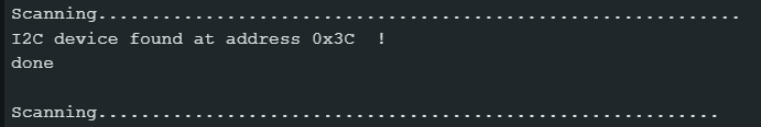

Hello, I would like to do the same assembly as you and I have a question. You say that for the assembly you use tmc 2209, but on the schematic on github, they are drv 8825. Is the code provided for tmc 2209 or for drv 8825 and is the schematic identical for tmc 2209. Thanks in advance