
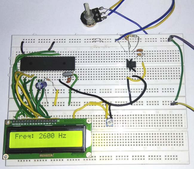
Frequency is defined as number of cycles per second. It can also be defined as reciprocal of total time ‘T’. In this project we are going to count the number of pulses entering into Port 3.5 of 8051 microcontroller and display it on 16*2 LCD display. So basically we have measuring the frequency of signal at Port 3.5 of 8051. Here we have used AT89S52 8051 chip, and a 555 IC is used in Astable mode for generating the sample pulse for demonstration. We have previously build Frequency counter using Arduino.
Components Required:
- 8051 microcontroller (AT89S52)
- 16*2 LCD display
- Frequency Source (555 Timer)
- Potentiometer
- Connecting wires
Circuit Diagram:


Using TIMER of 8051 for Measuring Frequency:
8051 microcontroller is a 8 bit microcontroller which has 128 bytes of on chip RAM, 4K bytes of on chip ROM, two timers, one serial port and four 8bit ports. 8052 microcontroller is an extension of microcontroller. To configure port 3.5 as counter, TMOD register values is set to 0x51. Below figure shows the TMOD register.
| GATE | C / T | M1 | M0 | GATE | C / T | M1 | M2 |
| TIMER 1 | TIMER 0 | ||||||
GATE - when GATE is set, the timer or counter is enabled only when the INTx pin is HIGH and TRx control pin is set. When GATE is cleared, the timer is enabled whenever TRx control bit is SET.
C / T – when C/T = 0, it acts as Timer. When C/T = 1, it acts as Counter.
M1 and M0 indicates mode of operation.
For TMOD = 0x51, timer1 is acts as counter and it operates in mode1 (16bit).
16*2 LCD is used to display the Frequency of the signal in Hertz (Hz). If you are new to 16x2 LCD, check more about 16x2 LCD’s pins and its commands here. Also check how to interface LCD with 8051.
555 Timer as Frequency Source:
The frequency source should produce square waves and the maximum amplitude is limited to 5V, because the ports of 8051 microcontroller cannot handle voltage greater than 5V. The maximum frequency it can measure is 655.35 KHz because of memory limitation of TH1 and TL1 register (8bit each). In 100 milliseconds, TH1 and TL1 can hold up to 65535 counts. Hence the maximum frequency that can be measured is 65535 * 10 = 655.35 KHz.
In this 8051 Frequency Meter project, I’m using 555 timer in astable mode to produce variable frequency square waves. The frequency of signal generated by 555 IC, can be varied by adjusting the potentiometer as demonstrated in the Video given at the end of this Project.
In this project, the Timer1 (T1) counts the number of pulses entering into port 3.5 of 8051 microcontrollers for 100 milliseconds. The count values will be stored in TH1 and TL1 registers respectively. To combine values of TH1 and TL1 register, the below formula is used.
Pulses = TH1 * (0x100) + TL1
Now the ‘pulse’ will have number of cycles in 100 milliseconds. But the frequency of the signal is defined as number of cycles per second. To convert it into frequency, below formula is used.
Pulses = Pulses * 10
Working and Code Explanation:
The complete C program for this Frequency Meter is given at the end of this project. The code is split into small meaningful chunks and explained below.
For 16*2 LCD interfacing with 8051 microcontroller, we have to define pins on which 16*2 lcd is connected to 8051 microcontroller. RS pin of 16*2 lcd is connected to P2.7, RW pin of 16*2 lcd is connected to P2.6 and E pin of 16*2 lcd is connected to P2.5. Data pins are connected to port 0 of 8051 microcontroller.
sbit rs=P2^7;
sbit rw=P2^6;
sbit en=P2^5;
Next we have to define some functions which are used in the program. Delay function is used to create specified time delay. Cmdwrt function is used to send commands to 16*2 lcd display. datawrtfunction is used to send data to 16*2 lcd display.
void delay(unsigned int)  ;
void cmdwrt(unsigned char);
void datawrt(unsigned char);
In this part of the code, we are sending commands to 16*2 lcd. Commands such as clear display, increment cursor, force the cursor to beginning of 1st line are sent to 16*2 lcd display one by one after some specified time delay.
   for(i=0;i<5;i++)
   {
     cmdwrt (cmd[i]);
     delay (1);
   }
In this part of the code, timer1 is configured as counter and mode of operation is set to mode 1.
Timer0 is configured as timer and mode of operation is set to mode 1. Timer 1 is used for counting the number of pulses and timer 0 is used for generating time delay. TH1 and TL1 values are set to 0, to ensure that counting starts from 0.
TMOD=0x51;
TL1=0;
TH1=0;
In this part of the code, timer is made to run for 100 milliseconds. 100 milliseconds of delay is generated using delay function. TR1=1 is for starting the timer and TR1=0 is for stopping the timer after 100 milliseconds.
TR1=1;
delay(100);
TR1=0;
In this part of the code, the count values present in TH1 and TL1 registers are combined and then it is multiplied with 10 to get the total number of cycles in 1 second.
Pulses = TH1*(0x100) + TL1;
Pulses = pulses*10;
In this part of the code, the frequency value is converted to single bytes to make it easy for displaying on 16*2 lcd display.
d1 = pulses % 10;
s1 = pulses % 100;
s2 = pulses % 1000;
s3 = pulses % 10000;
s4 = pulses % 100000;
d2 = (s1-d1) / 10;
d3 = (s2-s1) / 100;
d4 = (s3-s2) / 1000;
d5 = (s4-s3) / 10000;
d6 = (pulses-s4) / 100000;
In this part of the code, individual digits of frequency value is converted to ASCII format and the it is displayed on 16*2 lcd display.
If (pulses>=100000)
      datawrt ( 0x30 + d6);
if(pulses>=10000)
      datawrt( 0x30 + d5);
if(pulses>=1000)
      datawrt( 0x30 + d4);
if(pulses>=100)
      datawrt( 0x30 + d3);
if(pulses>=10)
      datawrt( 0x30 + d2);
datawrt( 0x30 + d1);
In this part of the code, we are sending commands to 16*2 lcd display. The command is copied to port 0 of 8051 microcontroller. RS is made low for command write. RW is made low for write operation. High to low pulse is applied on enable (E) pin to start command write operation.
void cmdwrt (unsigned char x)
{
   P0=x;
   rs=0;
   rw=0;
   en=1;
   delay(1);
   en=0;
}
In this part of the code, we are sending data to 16*2 lcd display. The data is copied to port 0 of 8051 microcontroller. RS is made high for command write. RW is made low for write operation. High to low pulse is applied on enable(E) pin to start data write operation.
void datawrt (unsigned char y)
{
   P0=y;
   rs=1;
   rw=0;
   en=1;
   delay(1);
   en=0;
}
This is how we can measure the frequency of any signal using 8051 Microcontroller. Check the full code and Demo Video below.
Complete Project Code
#include<reg51.h>

sbit rs=P2^7;
sbit rw=P2^6;
sbit en=P2^5;

void delay(unsigned int)  ;
void cmdwrt(unsigned char);
void datawrt(unsigned char);

void main (void)
{
unsigned long int pulses;
unsigned char i;
unsigned int s1,s2,s3,s4;
unsigned char d1,d2,d3,d4,d5,d6;
unsigned char cmd[]={0x38,0x01,0x06,0x0c,0x82};
unsigned char msg[]={"Freq: "};
unsigned char msg2[]={" Hz"};

    for(i=0;i<5;i++)
    {
      cmdwrt(cmd[i]);
  delay(1);
    }

while(1)
{
TMOD=0x51;
TL1=0;
    TH1=0;

TR1=1;

        delay(100);

TR1=0;

pulses= TH1*256 + TL1;
pulses=pulses*10;

d1=pulses%10;
s1=pulses%100;
s2=pulses%1000;
s3=pulses%10000;
s4=pulses%100000;

d2=(s1-d1)/10;
d3=(s2-s1)/100;
d4=(s3-s2)/1000;
d5=(s4-s3)/10000;
d6=(pulses-s4)/100000;

cmdwrt(0x01);
delay(1);

for(i=0;msg[i]!='\0';i++)
datawrt(msg[i]);

if(pulses>=100000)
datawrt(0x30+d6);
if(pulses>=10000)
datawrt(0x30+d5);
if(pulses>=1000)
datawrt(0x30+d4);
if(pulses>=100)
datawrt(0x30+d3);
if(pulses>=10)
datawrt(0x30+d2);
datawrt(0x30+d1);

for(i=0;msg2[i]!='\0';i++)
    datawrt(msg2[i]);
delay(1000);
}
}


void cmdwrt (unsigned char x)
{
   P0=x;
   rs=0;
   rw=0;
   en=1;
   delay(1);
   en=0;
}

void datawrt (unsigned char y)
{
   P0=y;
   rs=1;
   rw=0;
   en=1;
   delay(1);
   en=0;
}

void delay(unsigned int z)
{
  unsigned int p;
  for(p=0;p<z;p++)
  {
   TMOD=0X51;
   TH0=0xfc;
   TL0=0x66;
   TR0=1;
   while(TF0==0);
   TF0=0;
   TR0=0;
  }
}

Good