
With the advent of technology, our electronic gadgets and appliances are becoming smaller and smaller with more functional and complex applications. With this increase in complexity, the power requirement of the circuit has also increased and in our quest to make the device as small and as portable as possible, we need a battery which can provide high current for a long period of time and at the same time, weigh much less so that the device should remain portable. If you want to know more about batteries, you can also read this article on basic terminologies of battery.
Out of many different types of batteries available, Lead Acid batteries, Ni-Cd batteries, and Ni-MH batteries are not suitable as they either weigh more or cannot provide the current required for our application, this leaves us with the lithium-ion batteries which can provide high current while keeping the weight low and size compact. Previously we have also built a 18650 battery charger and booster module and an IoT based battery monitoring system, you can check them out if interested.
Why Do We Need a Battery Capacity Tester?
There are many battery vendors in the market selling the cheap knock off versions of Li-ion batteries claiming bizarre specifications with a very low price which is too good to be true. When you buy these cells either they do not work at all or if they do, the charge capacity or the current flow is so low that they cannot work with the application at all. So how to test a lithium battery if the cell is not one of these cheap knockoffs? One of the methods is to measure the open-circuit voltage at no load and loading but this is not at all reliable.
So we are going to build a 18650 battery capacity tester for a Li-Ion 18650 Cell which will discharge a fully charged 18650 cell through a resistor while measuring the current flowing through the resistor to calculate its capacity. If you do not get the claimed battery capacity while the cell voltage is within the specified limits, then that cell is faulty and you should not use that as the State of Charge of the cell will deplete at a very fast rate under load, creating a local current loop if used in a battery pack resulting in heating and possibly fire. So let’s jump right into it.
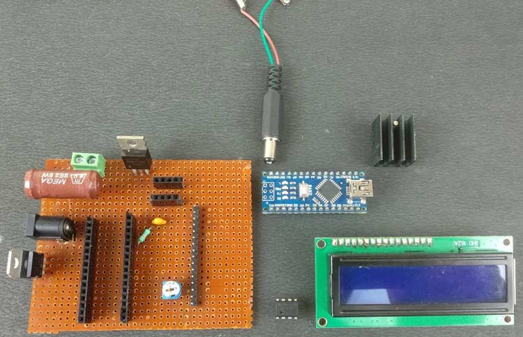
Components Required
- Arduino Nano
- 16×2 Character LCD
- LM741 OPAMP IC
- 2.2Ω, 5Watt Resistor
- 7805 Positive Voltage Regulator IC
- 12V Power Supply
- 10kΩ Trimmer Potentiometer
- 0.47uF Capacitor
- 33kΩ Resistor
- DC Power Barrel Jack Connector
- PCB Screw Terminals
- IRF540N N-Channel Mosfet IC
- Perfboard
- Soldering Kit
- Heat Sinks
Arduino Battery Capacity Tester Circuit Diagram
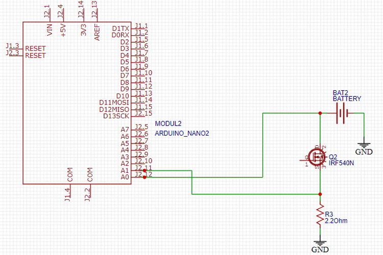
The complete circuit diagram for the 18650 battery capacity tester is shown below. The explanation of the circuit is as follows-

Computational and Display Unit:
This circuit is further divided into two parts, first is a low 5V supply for Arduino Nano and 16×2 Alphanumeric LCD screen and their connections to display the results of the current and voltage measurements in real-time. The circuit is powered by the 12V power supply using SMPS or you can use a 12V battery as well as the maximin current will be around 60-70mA for powering the Arduino and LCD screen.
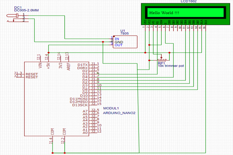
To step down the voltage down to 5V, we will use a which is a linear voltage regulator that can take up to 35V and need at least 7.5V input power supply to provide regulated 5V supply and excess voltage is dissipated as heat hence if your input voltage LM7805 Voltage Regulator IC is more than 12V, then consider adding a heat sink so that it doesn’t get damaged. The LCD is powered with a 5V supply from the 7805 and is connected to Arduino and working in 4-bit mode. We have also added a 10kΩ wiper potentiometer to control the contrast of the LCD display.
Constant Load Current Circuit:
Second is the PWM based constant current load circuit to make the load current flowing through the resistor controllable by us and constant so that there is no error creeping in due to current variation with time as the voltage of the cell goes down. It consists of LM741 OPAMP IC and IRF540N N-Channel MOSFET, which controls the current flowing through the MOSFET by switching ON and OFF the MOSFET according to the voltage level set by us.
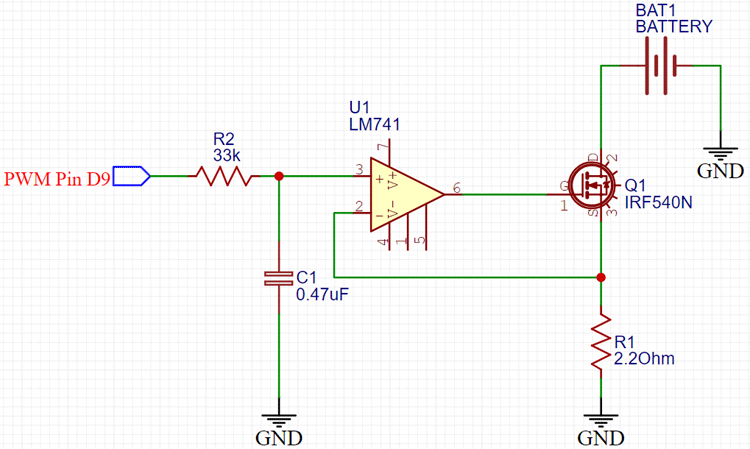
The op-amp is working in the comparator mode, so in this mode. the output of the op-amp will be high whenever the voltage of the non-inverting pin of the op-amp is higher than the inverting pin. Similarly, if the voltage at the inverting pin of the op-amp is higher than the non-inverting pin, the output of the op-amp will be pulled down. In the given circuit, the non-inverting pin voltage level is controlled by the D9 PWM pin of the Arduino NANO, which switches at 500Hz frequency which is then passed through low pass RC circuit filter with Resistance value 33kΩ and Capacitor having a capacitance of 0.47uF, to provide an almost constant DC signal at the non-inverting pin. The inverting pin is connected to the load resistor, which reads the voltage across the resistor and common GND. The output pin of the OPAMP is connected to the gate terminal of the MOSFET to switch it ON or OFF. The OPAMP will try to make the voltages on both its terminals equal by switching the MOSFET connected so the current flowing through the resistor will be proportional to the PWM value you have set at the D9 pin of the NANO. In this project, the maximum current, I have limited my circuit to is 1.3A which is reasonable as the cell I have is 10A as its maximum current rating
Voltage Measurement:
The Maximum voltage a typical fully charged Li-Ion cell is 4.1V to 4.3V which is less than the 5V voltage limit of the Analog input pins of the Arduino Nano which has more than 10kΩ internal resistance in them so that we can directly connect the Cell to any of the analog input pins without worrying about the current flowing through them. So, in this project, we need to measure the voltage of the cell so that we can determine whether the cell is in the correct voltage operating range and if it is fully discharged or not.
We need to measure the current flowing through the resistor as well for that we can’t use the current shunt as the complexity of the circuit will increase and increasing resistance in the load path will decrease the cell discharge rate. Using smaller shunt resistors will require an additional amplifier circuit to make the voltage reading coming from it, readable to the Arduino.
So we directly read the voltage across the load resistor and then using Ohm’s Law divides the voltage obtained by the load resistor value to get the current flowing through it. The negative terminal of the resistor is connected directly to the GND, so we can safely assume that the voltage we are reading on the resistor is the voltage drop in the resistor.
Arduino Program to Measure Battery Capacity
Now after finalizing the hardware circuit, we move to Arduino programming. Now if you don’t have Arduino IDE installed on your PC what are you doing here! Go to the official Arduino website and download and install the Arduino IDE or you can code in any other editor as well but that is a topic for another day for now we stick to Arduino IDE. Now we are using Arduino Nano, so make sure you have selected the Arduino Nano board by going to TOOLS> BOARDS and Selecting ARDUINO NANO there, now select the correct processor your nano have by going to TOOLS> PROCESSOR and while you are there also select the port your Arduino is connected to on your PC. We are using Arduino to drive the 16×2 Alphanumeric LCD connected to it and to measure the voltage of the cell and current flowing through the load resistor as explained in the previous section we start our code by declaring the header files to drive 16×2 Alphanumeric LCD screen. You can skip this section to get the fully cooked and served code at the end of the page but bear with us while we divide the code into small sections and try to explain.
Now that the header file is defined, we move on the declaring the variables, we will use in the code to calculate the voltage and current. Also, we have to define the pins we are using to drive the LCD and the pins we will be using to give PWM output and read the analog voltages coming from the cell and resistor as well in this section.
#include <LiquidCrystal.h>  //Default Arduino LCD Librarey is included
const int rs = 3, en = 4, d4 = 5, d5 = 6, d6 = 7, d7 = 8; //Mention the pin number for LCD connection
LiquidCrystal lcd(rs, en, d4, d5, d6, d7);
const float BAT_LOW = 3.0;    //to define the low voltage limit of the Li Ion cell
const float BAT_HIGH = 4.5;   //to define the high voltage limit of the cell
const int MOSFET_Pin=9;
const int PWM_VALUE=150;
unsigned long previousMillis = 0; // Previous time in ms
unsigned long millisPassed = 0;  // Current time in ms
float Capacity=0;     //Variable to define the battery Capacity
float Resistor=2.2;   // Load Resistor Value is 2.2ohms
float mA;
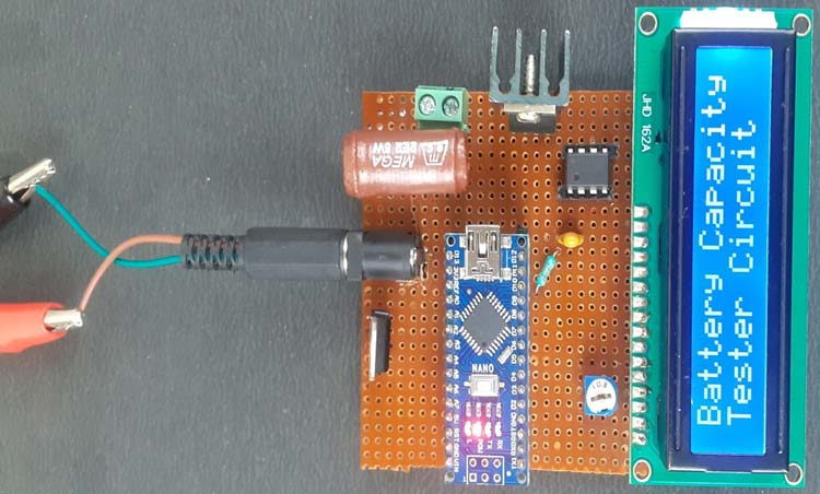
Now coming to the setup part, If you want to keep your Arduino connected to your PC the whole time and monitor the progress using Serial Monitor and initialize the LCD screen here. It will also display a welcome message “Battery Capacity Tester Circuit” on the screen for 3 seconds.
void setup()
{
  Serial.begin(9600);
  lcd.begin(16, 2);
  lcd.setCursor(0, 0); // Set the cursor on the first column and first row.
  lcd.print("Battery Capacity");
  lcd.setCursor(0,1);
  lcd.print("Tester Circuit");
  delay(3000);
  lcd.clear();
}
Now we do not need to declare the Arduino PWM pin as Output as the AnalogWrite function we are going to use in our main loop takes care of this part. You do need to define the PWM value to be written on that pin in the code. Select the PWM value carefully according to the discharge current required in your application. Too much PWM value will result in high current with a high voltage drop in the Li-Ion cell and too low PWM value will result in high discharging time of the cell. In the main loop function, we will be reading the voltages on the pins A0 and A1 as the Arduino has a 10-bit ADC on board hence we should get digital output values ranging from 0-1023 which we will need to scale back to the 0-5V range by multiplying it by 5.0/1023.0. Make sure you correctly measure the voltage between the 5V and GND pins of the Arduino Nano using a calibrated Voltmeter or Multimeter as most of the times the regulated voltage is not exactly 5.0V and even a small difference in this reference voltage would result in errors creeping in the voltage readings so measure the correct voltage and replace the 5.0 in the multiplier given above.
Now to explain the logic of the code, we continuously measure the voltage of the cell and if the cell voltage is over the upper limit specified by us in the code, then the error message is shown on LCD to let you know if the cell is overcharged or there is something wrong with the connection and the power to the MOSFET gate pin is stopped so that no current can flow through the load resistor. It is crucial that you fully charge your cell first before connecting it to the capacity tester board so that you can calculate its total charge capacity.
  analogWrite(MOSFET_Pin, PWM_VALUE);
  // read the input on analog pin 0:
  int sensorValue_voltage_Cell = analogRead(A0);
  // Convert the analog reading (which goes from 0 - 1023) to a voltage (0 - 5V):
  float voltage = sensorValue_voltage_Cell * (5.08 / 1023.0);
  Serial.print("VOLTAGE: ");
  Serial.println(voltage);      // Here the voltage is being printed on Serial Monitor
  lcd.setCursor(0, 0); // Set the cursor on the first column and first row.
  lcd.print("Voltage: "); // Print the voltage reading on the screen
  lcd.print(voltage);
 delay(100);
  int sensorValue_Shunt_Resistor= analogRead(A1);
  float voltage1= sensorValue_Shunt_Resistor *(5.08 / 1023.0);
  float current= voltage1/Resistor;
  Serial.print("Current: ");
  Serial.println(current);
  lcd.setCursor(0, 1); //Set the cursor on the first column and the second row (counting starts at 0!).
  lcd.print("Current: ");
  lcd.print(current);
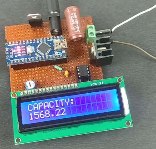
Now, if the cell voltage is within the upper and lower voltage limits specified by us then the Nano will read the Current value by the method specified above and multiply it with the time passed during the measurements and store it in the capacity variable we defined earlier in mAh units. During this whole time, the real-time current and voltages values are being displayed on the LCD screen attached, and if you want, you can also see them on the serial monitor. The process of discharging the cell will continue until the cell’s voltage reach below the lower limit specified by us in the program and then the total capacity of the cell is displayed on the LCD screen and current flow through the resistor is stopped by pulling the MOSFET gate pin low.
else if(voltage > BAT_LOW && voltage < BAT_HIGH  )
  { // Check if the battery voltage is within the safe limit
      millisPassed = millis() - previousMillis;
      mA = current * 1000.0 ;
      Capacity = Capacity + (mA * (millisPassed / 3600000.0)); // 1 Hour = 3600000ms to convert it into mAh units
      previousMillis = millis();
      delay(1000);
      lcd.clear();
     }
Accuracy Improvements
It is, by all means, a good enough way to read voltage and current, but it is not perfect. The relationship between the actual voltage and measured ADC voltage is not linear and this will amount to some error in the measurements of the voltages and currents.
If you want to increase the accuracy of the result, then you must plot the ADC values you get from applying various known voltage sources on a graph and then determine the multiplier equation from it by using any method you like. This way, accuracy will be improved, and you will get very close to actual results.
Also, the MOSFET we used is not a logic-level MOSFET, so it needs more than 7V to fully turn on the current channel and if we apply 5V directly to it, the current readings would be inaccurate. But you can use a logic level IRL520N N-Channel MOSFET to eliminate the use of a 12V supply and directly work with 5V logic levels you have with your Arduino.
Building and Testing the Circuit
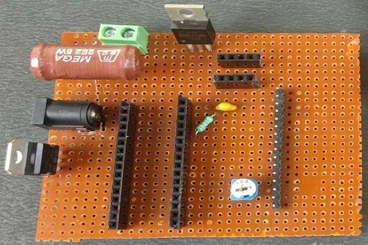
Now as we designed and tested different sections of our circuit on a breadboard and after making sure that all of them are working as intended we use a Perfboard to solder all the components together as it is a much more professional and reliable method to test the circuit. If you want, you can design your own PCB on AutoCAD Eagle, EasyEDA, or Proteus ARES or any other software you like. The Arduino Nano, 16×2 Alphanumeric LCD, and LM741 OPAMP are mounted on Female Bergstik so that they can be reused later.
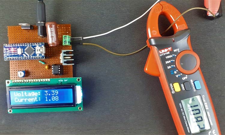
I have provided a 12V supply through a DC Barrel Jack connector for Constant Load Current Circuit and then with the help of LM7805, the 5V for the Nano and LCD screen is provided. Now power the circuit and adjust the trimmer pot to set the contrast level of the LCD screen, you should see the Welcome Message on the LCD screen by now, and then if the voltage level of the cell is in the working range, then the current-voltage and current from the battery will be displayed there.
This is a very basic test to calculate the capacity of the cell you are using and it can be improved by taking the data and storing it in an Excel file to do post data processing and visualization by graphical methods. In today’s data-driven world, this cell discharge curve can be used to build accurate predictive models of the battery to simulate and see the response of the battery under loading condition without real-world testing by using Software like NI LabVIEW, MATLAB Simulink, etc. and a lot more applications awaits you. You can find the complete working of this project in the video below. If you have any questions about this project, please write them in the comment section below or use our forums. Go and have fun with it and if you want, we can guide you in the comments section below on how to proceed further from here. Till then Adios!!!
Complete Project Code
#include <LiquidCrystal.h>  //Default Arduino LCD Librarey is included
const int rs = 3, en = 4, d4 = 5, d5 = 6, d6 = 7, d7 = 8; //Mention the pin number for LCD connection
LiquidCrystal lcd(rs, en, d4, d5, d6, d7);
const float BAT_LOW = 3.0;    //to define the low voltage limit of the Li Ion cell
const float BAT_HIGH = 4.5;   //to define the high voltage limit of the cell
const int MOSFET_Pin=9;
const int PWM_VALUE=50
;
unsigned long previousMillis = 0; // Previous time in ms
unsigned long millisPassed = 0;  // Current time in ms
float Capacity=0;     //Variable to define the battery Capacity
float Resistor=2.2;   // Load Resistor Value is 2.5ohms
float mA;
void setup() {
  // initialize serial communication at 9600 bits per second:
  Serial.begin(9600);
  lcd.begin(16, 2); //Initialise 16*2 LCD
  lcd.setCursor(0, 0); // Set the cursor on the first column and first row.
  lcd.print("Battery Capacity");
  lcd.setCursor(0,1);
  lcd.print("Tester Circuit");
  delay(3000);
  lcd.clear();
}
void loop() {
  analogWrite(MOSFET_Pin, PWM_VALUE);
  // read the input on analog pin 0:
  int sensorValue_voltage_Cell = analogRead(A0);
  // Convert the analog reading (which goes from 0 - 1023) to a voltage (0 - 5V):
  float voltage = sensorValue_voltage_Cell * (5.12 / 1023.0)*1.2;
  Serial.print("VOLTAGE: ");
  Serial.println(voltage);      // Here the voltage is being printed on Serial Monitor
  lcd.setCursor(0, 0); // Set the cursor on the first column and first row.
  lcd.print("Voltage: "); // Print the voltage reading on the screen
  lcd.print(voltage);
  delay(100);
  int sensorValue_Shunt_Resistor= analogRead(A1);
  float voltage1= sensorValue_Shunt_Resistor *(5.00 / 1023.0);
  float current= voltage1/Resistor;
  Serial.print("Current: ");
  Serial.println(current);
  lcd.setCursor(0, 1); //Set the cursor on the first column and the second row (counting starts at 0!).
  lcd.print("Current: ");
  lcd.print(current);
  if ( voltage > BAT_HIGH)
  {
    digitalWrite(MOSFET_Pin, LOW);    // Turned Off the MOSFET , No discharge
    Serial.println( "Warning High-V! ");
    lcd.clear();
    lcd.setCursor(0,0);
    lcd.print("HIGH VOLTAGE!!");
    delay(2000);
    lcd.clear();
  }
  else if(voltage < BAT_LOW)
  {
      digitalWrite(MOSFET_Pin, LOW);      // Turned Off the MOSFET , No discharge
      Serial.println( "Warning Low-V! ");
      lcd.clear();
      lcd.setCursor(0,0);
      lcd.print("Low Voltage!!!");
      delay(2000);
      lcd.clear();
      lcd.setCursor(0,0);
      lcd.print("CAPACITY:");
      lcd.setCursor(0,1);
      lcd.print(Capacity);
      delay(10000);
  }
  else if(voltage > BAT_LOW && voltage < BAT_HIGH  )
  { // Check if the battery voltage is within the safe limit
      millisPassed = millis() - previousMillis;
      mA = current * 1000.0 ;
      Capacity = Capacity + (mA * (millisPassed / 3600000.0)); // 1 Hour = 3600000ms to convert it into mAh units
      previousMillis = millis();
      //Serial.print("DATA,TIME,"); Serial.print(voltage); Serial.print(","); Serial.println(Capacity);       //uncomment this line to diplay on serial monitor
      delay(1000);
      lcd.clear();
     }
}Comments
Looks like something I want to build. I'm curious if this tester would also work with the 21700 or any other cell ? I can't see why not although I haven't read over the entire project. Obviously algerithums are being used. I have worked with battery testers for auto batteries that were alerithum based, it didn't matter what size battery with those as they could be calibrated for the size of battery and unlike the old school testers that used heaters and meters, analogue dearsevol movement meters, these are non destructive.
Also in the beginnig of the article it shows 2 tester circuits connected together, one is reading something and the other another display. I didn't see anything in the text indicating why there were 2 identical boards. Later on in the post I conclude that only 1 board is needed, yet I still wonder why 2 boards then only 1 board.
Not that this is a big deal as if anyone that has knowledge and done electronic construction before should have already caught on to it. The pictorial drawing shows the left pin of the 7805 as the Grnd pin and that pin is actually the input pin. The center pin is the Grnd and the right pin is the output. The schematic would give the proper wiring so the circuit would be functional. Obviously if anyone followed the colored pict layout the Vreg would short out and explode. I believe the circuit should have configured with polarity protection diodes simply for the purpose of piece of mind. I myself seldom ever construct a Vreg circuit without doing this, simply one diode to the input or the use of 2, 1 to the input anode to +V cathode to input and the other from the output to the input, cathode to input anode to output. Also seen there are no capacitors included in the +V input and or regV from the output. It seems to me this is just good practice to deal with transients even if the odds of those are little to none. Since these circuits are powered by supplies, that chance is higher than with batteries and even then we live with so much electro induced radiation around us, I like to have as much protection as possible.
I'm looking at the schematics and on the drawing of the LCD and wondering why in one schematic it labels the 2.2 R as R1 and in the other it is R3 ? Also there is a Bat 1 and Bat 2 which appears to be the same Bat, the one under test. Doesn't anyone proof read what they post ? Then there is another thing. I have been trying to get this projects code to go through and it will not even load into my Arduino sketch beyond the about the 3rd or 4th line before errors.
To the person that posted this ! I think you need to go back and check the pin numbering for the Nano and the LCD as from what I'm seeing it does add up, your colored pic does not match with your schematic which needs some help.I'm going to have to somewhere else to figure this out. Fr those who wish to build this, they are going to run into issues. There cannot be 2 pin on each chip with the same ID.
I would like to choose the current size something like 2 or 1,5 Amperes . I want to choose an USB connection with uart .
Ic741. Pin 7 is +12v?
I want to develop same thing for 48V battery.
What changes do i have to make for it?

Great! thank you. how to I measure voltage if connect few of these cells in series (i.e 11.1v)?