
The Joule Thief Circuit is a simple and clever electronic design that can power an LED using a nearly dead battery. The project demonstrates how basic components like a transistor, a toroidal coil, and a resistor can work together to boost a low input voltage to a usable output voltage. By building this circuit, we can explore how a nearly dead battery's energy can be used efficiently without wasting the energy in it. A Joule Thief circuit is a simple voltage booster that uses a toroidal coil, an NPN transistor, and a resistor to extract power from nearly dead batteries. It is a great project for understanding how inductive switching, voltage boosting, and energy-efficient design can be in a practical way.
For a deeper understanding of boost converter concepts, including switching operation, design principles, and efficiency considerations, refer to Switching Boost Regulator: Design Basics and Efficiency. This resource provides clear explanations of how switching regulators work and how voltage boosting is achieved efficiently in practical circuits.
Table of Contents
- What is a Joule Thief Circuit
- Complete Parts List
- Schematic Explained
- Wiring Diagram
- Working Principle
- └ ⇒ Phase 1: Current Flows in the Primary Coil
- └ ⇒ Phase 2: Feedback Coil Activates the Transistor
- └ ⇒ Phase 3: Core Saturation Occurs
- └ ⇒ Phase 4: Magnetic Field Collapse & High Voltage Spike
- └ ⇒ Phase 5: Oscillation Begins Again
- Simulation
- Practical Working Demonstration
- └ Circuit Implementation
- What are some alternatives to the Joule Thief circuit?
- Advantages and Disadvantages
What is a Joule Thief Circuit
A Joule Thief circuit is a small, energy-efficient boost converter designed to extract usable power from very low-voltage sources such as “dead” or nearly drained batteries. It uses a transistor, a resistor, and a toroidal coil with two windings to step up the low input voltage and generate high-voltage pulses. These pulses are strong enough to power devices like LEDs, even when the battery voltage is too low to operate them directly.
The joule thief circuit working mechanism relies on rapid switching, turning the transistor ON and OFF many times per second, which stores and releases energy in the coil. This simple circuit is widely used to demonstrate energy harvesting, inductive switching, and efficient power utilisation, making it popular in hobby electronics, education, and low-power lighting applications. This joule thief circuit with toroid operates through self-sustained oscillation, rapidly switching the transistor between conduction and cutoff states thousands of times per second.
Joule Thief Circuit Components: Complete Parts List
The Joule Thief circuit has a minimal set of electronic components that are easy to obtain and assemble. Below the detailed table explaining each component and its purpose in the circuit.
| Components | Quantity | Description | Function in Circuit |
| NPN Transistor (eg.2N2222,2N3904) | 1 | A small-signal transistor | Acts as a switch, controlling current flow through the coil and enabling voltage boosting |
| 1 kΩ Resistor | 1 | Limits current to the transistor base | Prevents excessive base current and ensures stable oscillation |
| Toroidal Coil | 1 | Small ferrite core with two windings | Stores and releases magnetic energy; provides feedback to the transistor for oscillation |
| LED | 1 | Light Emitting Diode | Converts boosted voltage pulses into visible light |
| Battery (AA or AAA, 1.5V) | 1 | Low-voltage power source | Provides input voltage, even if weak or partially discharged |
| Breadboard | 1 | prototyping board | Allows easy assembly and testing of the circuit without soldering |
| Connecting Wires | As needed | copper or jumper wires | Connects components to form the complete circuit |
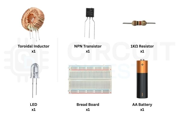
The image below displays all joule thief circuit components required for construction. It includes a toroidal inductor for energy storage, an NPN transistor for high-speed switching, a 1 kΩ resistor to control base current, an LED as the load, an AA battery as the low-voltage source, and a breadboard for easy prototyping and testing of the circuit. If you want to learn more about what an NPN transistor is and how it works, check out the article “NPN Transistors.”
Joule Thief Circuit Diagram: Schematic Explained
The joule thief circuit diagram shows how the transistor, resistor, LED, and the two windings on the toroid are connected. It clearly illustrates how the Joule Thief boosts a low battery voltage to power the LED.

This Joule thief schematic clearly illustrates a simple Joule Thief circuit, showing how a low-voltage battery can be boosted to light an LED. In this setup, the core component is a Joule Thief circuit with a toroid, where the toroidal core carries two windings: the primary winding (1 & 2) for current flow and the feedback winding(3 & 4) for rapid switching. This layout helps you understand how the coil windings and the transistor work together to step up the voltage efficiently from even a nearly drained battery. This joule thief circuit diagram demonstrates the critical relationship between components.
Joule Thief Wiring Diagram: Practical Assembly Guide
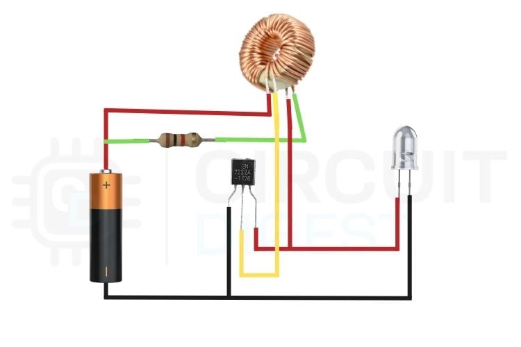
This wiring diagram shows the practical implementation of the joule thief circuit with toroid, with clearly distinguished coil connections. The primary winding, which carries the main current from the battery, is shown using the red wire, while the feedback (switching) winding, which provides base drive to the transistor, is indicated using the yellow wire. The correct interaction between these two windings enables rapid transistor switching and voltage boosting to power the LED from a low-voltage battery.
Joule Thief Circuit Working Principle
Understanding the joule thief circuit working requires examining the electromagnetic interactions between the toroidal coil windings and the transistor switching behaviour. The Joule Thief uses a Toroidal coil with two windings :
1. Primary Coil - carries the main current from the battery
2. Feedback (switching) Coil - controls the transistor switching
Both coils work together to create a self-oscillating boost converter
⇒ Phase 1: Current Flows in the Primary Coil
When the battery is connected, a small current starts to flow through the primary coil and then to the transistor’s base through the resistor. This turns the transistor slightly ON, allowing current to flow through it. The magnetic field starts building in the primary coil due to the flow of current around the toroid.
⇒ Phase 2: Feedback Coil Activates the Transistor
As the magnetic field builds around the primary coil, it induces a voltage in the feedback(switching) coil. This process occurs due to the mutual inductance. The induced voltage is passed into the transistor, increasing the base current.
As a result, the transistor turns more ON, allowing more current to flow through the primary coil.
This is called the positive feedback, and it forces the transistor to full conduction.
⇒ Phase 3: Core Saturation Occurs
As current continues to flow through the primary winding, the magnetic field in the toroidal core keeps increasing until the ferrite core can no longer store additional magnetic flux. This condition is known as Magnetic Saturation.
Once the core reaches saturation, the induced voltage in the feedback coil starts to drop sharply, causing the base drive of the transistor to disappear. As a result, the transistor switches OFF abruptly.
⇒ Phase 4: Magnetic Field Collapse & High Voltage Spike
When the transistor switches OFF, the current flowing through the primary coil cuts off suddenly.
But the inductors resist the sudden change in the current flow, so the magnetic field collapses rapidly, which is stored in the primary coil.
This collapse creates a high voltage spike across the primary coil. This spike is much higher than the original battery voltage and is enough to light up an LED.
⇒ Phase 5: Oscillation Begins Again
Once the transistor switches OFF, the current flow through the primary winding stops and the magnetic field in the toroid collapses to ZERO. After this, a small amount of current starts again to flow across the coil and into the transistor’s base through the resistor. This initiates the next switching cycle.
This repeated action causes the primary and feedback windings to continuously force the transistor to turn ON and OFF at high frequency. The frequency is between the hundreds and thousands of times per second, which produces rapid voltage pulses that keep the LED illuminated.
Joule Thief Circuit Simulation: Visual Working Demonstration
Here is the Simulation of the simple Joule thief circuit. It demonstrates how a low-voltage battery is able to power an LED through the rapid switching and voltage boosting. At the beginning, the current starts to flow through the primary winding, causing the transistor to switch ON. The feedback wing then reinforces the base drive, which results in rapid oscillation. The following simulation demonstrates the joule thief circuit working principles in real-time.
As seen in the simulation of the Joule Thief schematic, once the magnetic core reaches saturation, the transistor switches OFF, and the stored magnetic energy collapses, which results in a high-voltage spike across the primary winding. This voltage spike is sufficient to forward-bias the LED, allowing it to glow even though the battery voltage is very low.
The continuous ON & OFF switching cycle is clearly visible in the simulation, and it proves the self-oscillating nature of the Joule Thief Circuit and its ability to efficiently boost voltage from weak power sources.
Practical Working Demonstration: Video Evidence
This practical demonstration showcases a real-world joule thief circuit working behaviour. The LED does not glow when connected directly to the low-voltage battery, but it lights up when connected through the Joule Thief circuit. This happens due to rapid switching and voltage boosting using the toroidal coil. The demonstration confirms the circuit’s ability to utilise energy from weak batteries.
In the above video, the LED is directly connected to the battery, but it does not glow. This happens because the battery voltage is too low to overcome the LED’s forward voltage requirement. Although the battery still contains some energy, it is insufficient to drive current through the LED directly. This observation highlights the limitation of low-voltage sources and sets the foundation for using the Joule Thief circuit, which boosts the voltage and enables the LED to glow even from a weak battery.
Joule Thief Circuit Implementation

When the LED is connected through the Joule Thief circuit with toroid, it starts glowing even with the same low-voltage battery. This is because the circuit boosts the battery’s voltage by rapidly switching the transistor and storing energy in the toroidal coil. The collapsing magnetic field generates high voltage pulses that are sufficient to forward bias the LED. This result clearly demonstrates the effectiveness of the Joule Thief circuit in extracting and utilising the remaining energy from weak batteries.
Practical Applications of Joule Thief Circuits
- Powering LEDs from weak batteries - It can light an LED even when the battery voltage is too low for normal use.
- Energy harvesting projects - Useful for extracting leftover energy from partially drained cells.
- Portable emergency lights - Can be used in small flashlights to extend battery life.
- Educational and hobby electronics - Helps students understand inductive switching, oscillation, and voltage boosting.
- Low-power sensor circuits - Can drive small sensors or circuits that require a slightly higher voltage.
- Battery testing demonstrations - Shows visually how much energy remains in “dead” batteries.
What are some alternatives to the Joule Thief circuit?
∗ Supercharged Joule Thief circuit: The supercharged Joule Thief has a higher efficiency (greater than 80%) than other types of Joule Thief circuits that range from 40-60% efficiency.
∗ Buck-Boost Converters: Used for more powerful applications with a negative voltage output from an input voltage.
∗ Voltage multiplier: Converts lower-voltage AC electricity into DC electricity of a higher voltage.
∗ Split-pi Topology: DC-DC converters that have bidirectional capabilities due to the use of MOSFETs and are suited for regenerative braking systems.
Advantages and Disadvantages of the Joule Thief Circuit
| Advantages | Disadvantages |
| Can operate from very low input voltages | Can operate from very low input voltages |
| Utilizes energy from weak or “dead” batteries | Output voltage is unregulated |
| Simple circuit with very few components | Not suitable for high-current loads |
| Low cost and easy to build | Efficiency drops at higher loads |
| Self-oscillating (no external controller needed) | Generates electrical noise due to switching |
| Ideal for learning voltage boosting concepts | Cannot be used for battery charging |
| Compact and portable design | Performance depends on coil winding quality |
Technical Limitations of the Joule Thief Circuit
- Low Output Power:
The Joule Thief can only deliver a small amount of power, making it suitable only for low-power loads such as LEDs. - Poor Voltage Regulation:
The output voltage is not regulated and appears as high-voltage pulses, which are unsuitable for sensitive electronic devices. - Low Efficiency at Higher Loads:
Efficiency decreases significantly when attempting to drive higher current or multiple loads. - Limited Current Capability:
The circuit can boost voltage, but cannot supply high current. - Component Sensitivity:
Performance depends heavily on the type of transistor, coil winding, and core material. - EMI and Noise:
Rapid switching can generate electrical noise and electromagnetic interference.
Frequently Asked Questions About Joule Thief Circuit
⇥ 1. What is the minimum battery voltage needed?
The circuit can often run from as low as 0.8V, depending on components.
⇥ 2. Why is it called a “Joule Thief”?
Because it “steals” the remaining energy (joules) from weak or “dead” batteries and makes them usable again.
⇥ 3. Why is a toroidal core used?
The toroid helps create strong magnetic coupling between the two windings, making the switching process efficient.
⇥ 4. Can I use any NPN transistor?
Most general-purpose NPN transistors (like 2N3904, BC547, or 2N2222) will work.
⇥ 5. How does the circuit boost voltage?
It uses a transistor and a two-winding coil to store energy in a magnetic field and release it as high-voltage pulses when the transistor switches OFF.
⇥ 6. Why does the circuit oscillate automatically?
Because the feedback winding sends a signal that rapidly turns the transistor ON and OFF, creating a self-sustaining oscillation cycle.
⇥ 7. Can the Joule Thief charge batteries?
Not directly. It boosts voltage but does not regulate current, so it's not suitable for battery charging without modifications.
⇥ 8. What is the typical operating frequency range of a Joule Thief circuit?
Joule Thief circuits normally operate at oscillation frequencies between 50 and 500 kHz, which are mainly influenced by various factors such as the type of core used for the toroid, the number of turns in the winding, the properties of the transistor, and the load applied.
This tutorial was created by the CircuitDigest engineering team. Our experts focus on creating practical, hands-on tutorials to help makers and engineers learn Raspberry Pi projects, Arduino projects, Electronic Circuit projects and more.
I hope you liked this article and learned something new from building the Joule Thief circuit. If you have any doubts, you can ask in the comments below or use our CircuitDigest forum for a detailed discussion.
Related Beginner Electronics Projects
A simple collection of beginner-friendly electronics circuits and concepts, covering LED control, 555 timer applications, boost converters, and basic transistor operation.

Single Cell Boost Converter Circuit using Coin Cell – 5V Output
In this project, we build a low-cost 5V booster circuit that provides a constant regulated output voltage of 5V from a CR2032 coin cell.

A Simple DC-DC Boost Converter using 555 Timer IC
In this project, we build a simple boost converter circuit using a 555 timer IC. A boost converter is a non-isolated type of switch-mode power supply that is used to step up the voltage.

Simple Flashing LED using 555 Timer IC
This tutorial will show you how to make an LED glow and fade on a certain interval. So here is the step by step guide to make this flashing LED circuit.

This tutorial shows how to design a high-power LED driver circuit using the LM317 IC. It covers current limiting basics, resistor calculations, power ratings, and practical breadboard testing for reliable LED operation.
Comments
Your explanation of the circuit is incorrect
Secondly you can add a capacitor to make the circuit much more efficient
The picture shown in the "Practical Assembly Guide" is wrong. If we follow the schematic diagram, the red wire (#1) and the yellow wire (#4) must be connected to the (+) of the battery.
The green wire of the 1K resistor must be connected to the base of the NPN transistor.

can you make and send one, we need one for extremely low voltage 50mV to 3V.