

There are many situations when our circuit design has two power sources such as an adapter and a battery or it can even be two other power supplies from two different outlets. The requirement of the application can be something like it should always need to remain ON during power failures by using and additional power source that is available. For example, a circuit that is powered using an adapter needs to switch to a battery or an auxiliary power supply without interrupting the operation of the circuit in the event of a power failure.
In these above-mentioned cases, a Power Path Controller Circuit will be helpful. Basically, a power path control circuit will switch the main power of the circuit board depending on the power source available by controlling the path from where the power comes into the circuit.
In this project, we will build a dedicated power path controller system that will switch the power input of the load from primary power to the auxiliary power during the primary power failure and also again change the power source auxiliary to primary during the primary power restored phase. This is a very essential circuit to be built to support the uninterrupted power supply application state during the input power is changing from primary to auxiliary or auxiliary to the primary. In other words, it can work like UPS for Arduino and Raspberry Pi Projects and it can also be used for multiple batteries charging from a single charger.
Requirements
The requirement of the circuit is specified as below-
- The load current will be up to 3A.
- The maximum voltage will be 12V for an adapter (primary power) and 9V as a battery (secondary power)
LTC4412 Power Path Controller
The main controller that is selected for the circuit is the LTC4412 from Analog Devices (linear technologies). This is a low-loss power path controller system that automatically switches between two DC sources and simplifies the load sharing operations. As this device supports adapter voltage ranges from 3 volts to 28 volts and supports battery voltage ranges from 2.5 volts to 25 volts. Thus, it serves the above requirement of the input voltage. In the below image, the pinout diagram of LTC4412 is shown-
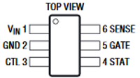
However, it has two input sources, one is the primary, and the other one is the auxiliary. The primary power source (Wall adapter in our case) has priority over the auxiliary power source (battery in this case). Therefore, whenever the primary power source is present, the auxiliary power source will automatically get disconnected. The difference between these two input voltages is only 20mV. Thus, if the primary power source gets 20mV higher than the auxiliary power source, the load gets connected with the primary power source.
The LTC4412 has two additional pins - Control and status. The control pin can be used to digitally control the input to force the MOSFET to turn off, whereas the status pin is an open-drain output pin that can be used to sink 10uA of current and can be used to control an additional MOSFET with an external resistor. This can also be interfaced with a microcontroller for getting the presence signal of the auxiliary power source. LTC4412 also provides reverse polarity protection for the Battery. But since we are working with power supplies, here you can also check out other designs like Over Voltage Protection, Over current Protection, Reverse polarity Protection, Short Circuit Protection, Hot Swap controller, etc. which might come in handy
Another component is to use two P-Channel MOSFETs for controlling the auxiliary and primary power sources. For this purpose, FDC610PZ is used as a P channel, -30V, -4.9A MOSFET that is suitable for the operation of 3A of load switching. It has a low RDSON resistance of 42 mili-ohms which makes it suitable for this application without an additional heat sink.
Therefore, the detailed BOM is-
- LTC4412
- P-Channel MOSFET- FDC610PZ - 2 pcs
- 100k resistor
- 2200uF capacitor
- Relimate connector - 3 pcs
- PCB
LTC4412 Power Path Controller Circuit Diagram

The circuit has two operating conditions, one is the loss of primary power and the other one is the recovery of primary power. The major job is done by the controller LTC4412. The LTC4412 connects the output load with the auxiliary power whenever the primary power voltage falls 20 mV less than the auxiliary power voltage. In this situation, the status pin sinks current and turns on the auxiliary MOSFET.
In other working conditions, whenever the primary power input goes 20 mV above the auxiliary power source, the load is again gets connected with the primary power source. The status pin then goes into the open-drain condition and will turn off the P-Channel MOSFET.
These two situations not only automatically change the power source depending on the primary power failure but also makes switchover if the primary voltage drops significantly.
The sense pin provides power to the internal circuitry if the VIN does not get any voltage and also senses the voltage of the primary power supply unit.
The larger output capacitor of 2200uF 25V will provide sufficient filtration during the switch off phases. At the small duration time when the switch over will took place, the capacitor will provide power to the load.
PCB Board Design
To test the circuit, we need a PCB because the LTC4412 IC is in the SMD package. In the below image, the top side of the board is shown-
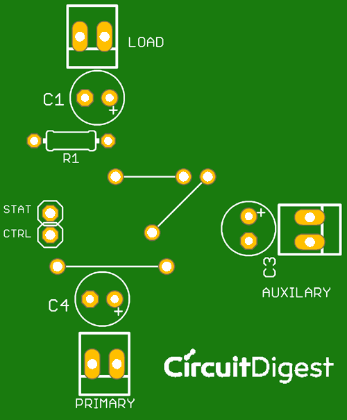
The design is done as a single-sided board. There are 3 wire jumpers also required in the PCB. Two additional optional inputs and output pins are also provided for the control and status related operations. A microcontroller unit can be interfaced in those two pins if required, but we won’t be doing that in this tutorial.
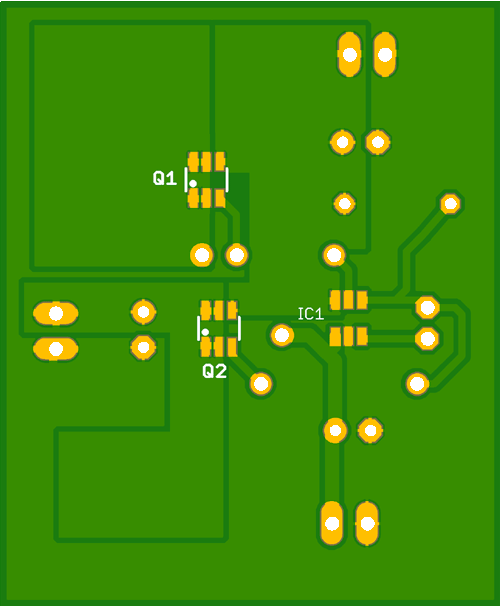
In the above image, the bottom side of the PCB is shown where two MOSFETs of Q1 and Q2 are displayed. However, the MOSFETs do not require additional heat sinks but in the design, the PCB heat sink is created. These will reduce the power dissipation across the MOSFETs.
Power Path Controller Testing
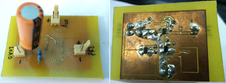
The two above images are showing the PCB of the power path controller that was designed previously. However, the PCB is a hand-etched version and it will serve the purpose. The components are being soldered properly in the PCB.
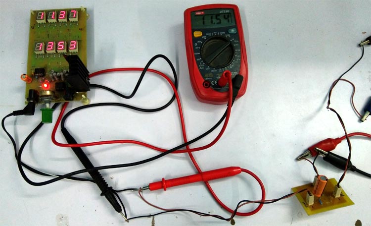
To test the circuit, an Adjustable DC load is connected across the output that is drawing almost 1 Amp of current. If you don’t have a Digital DC load, you can also build your own Adjustable DC load using Arduino.
For testing purposes, I faced a shortage of the battery (it’s COVID-19 lockdown here), and hence a bench power supply is used that has two outputs. One channel is set to 9V and the other one is set to 12V. The 12V channel is disconnected to see the result on the output and reconnected the channel to check the performance of the circuit.
You can check out the video linked below for the detailed demonstration of how the circuit works. I hope you enjoyed the project and learned something useful. If you have any questions, leave them in the comment section below or use our forums for other technical questions.
Comments
Hi Sourav,
One more query in regards to the circuit:
Could you kindly explain why in the circuit diagram the pin outs for Ctrl and Stat are shown. ut i think the pin outs are not used. Also CTRL does not seem to have been used in the circuit at all? Am i correct?
Hello Sourav Sir,
I am sanjay from india.
I couldn't get good source to buy these components FDC610PZ , LTC4412 in indian market.
Can you please share the source , where I can buy these components.
On other website the cost is v high.
Is there any alternative of these components which is easily available ?
Second:
Power path controller system that automatically switches between a Battery and e.g SMPS.
As a Product, charging of battery is also important important.
1. Is 18650 battery, suitable to use for AVR microcontroller ? or we need two 18560 cells?
2. TP4056 can be used to charge 18650 , if single cell is used ?

Hi Sourav,
Can you please provide links from where you could procure the LTC 4412 and P channel MOSFETs.
Also, there are couple of questions:
1. In the circuit diagram there are two more capacitors, C3 and C4, so what are their uses and values?
2. In the circuit diagram, only two Mosfets are shown, however, in the picture i could see 3 Mosfets?