

Although there are inverters and generators to immediately start the AC power supply whenever there is a power cut but sometime when there is no backup support and we have some critical machines running to perform some important task, it’s a good idea to atleast have an alarm which notify us as soon as power goes off. In this tutorial, we will learn how to make a simple Power Failure Alarm Circuit. This circuit can be used in many applications.
Required Components
- Relay (12VDC)
- 2000µF and 0.1 µF Capacitors
- Buzzer
- Bridge Diode
- Transformer
- Perfboard
- 1n4007 Diode
Relay
Relay is a switching device which can be operated either electronically or electromechanically. It is a 5 terminal device which is made up of electromagnets, movable armature, contacts, yoke and a frame. It works on the principle of magnetic property of inductor. So, when the inside coil gets energized then a magnetic field is generated around it and pulls the armature to connect the normally open terminal (NO) to Common (COM) terminal as shown in the image below.

To learn more about relay and its working, follow the link.
In this power failure alarm, we are using the relay to switch between two circuits - capacitor charging circuit and capacitor discharging circuit (capacitor-buzzer circuit).
Transformer
Here we are using a step-down center tapped 12-0-12 transformer. The center tapped transformer is similar to the normal transformer. It is just having an additional wire at the center of the secondary coil where, the voltage is zero. It implies that if we use a 12-0-12 transformer, then the voltage across the first two terminals or last two terminals will be 12V but the voltage across the first and the last terminal will be 24V. Its operation is also similar to normal transformer. A primary voltage induced in primary coil causes a secondary voltage in secondary coil, due to magnetic induction.

To learn more about Transformer and its various types, follow the links.
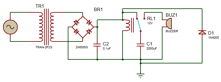
Circuit Diagram and Explanation
Circuit for this Mains Supply Failure Alarm is simple. You just need to follow the circuit diagram and solder it up on perfboard. Firstly a capacitor of 2000µF is connected between the common terminal of the relay and the ground. Then a buzzer is connected with positive terminal connected to normally connected (NC) and negative terminal to the ground.
A bridge rectifier diode is used to convert the Alternating current into Direct current. Connect the positive and negative terminal of the diode to positive and negative terminal of relay and the AC terminals to the AC power supply. Also connect a diode (1n4007) in reverse bias with relay. This diode D1 is called Freewheel diode. It blocks any reverse voltage developed in relay to prevent any accident. A 0.1µF capacitor is used to smooth out the output DC voltage.

Working of Power Supply Failure Alarm
After soldering the components as per circuit diagram, connect the power supply and turn it on. Then to check the system, turn off the power supply and you will see buzzer start beeping as soon as you turn off the power. The working is same like an emergency light, which also turns on as soon as the power goes off.
The working of the circuit is also very simple. When we turn on the supply, transformer converts the 220v AC to 12v AC. Then, the current coming from transformer is rectified by the bridge rectifier diode. The bridge rectifier consists of four rectifier diodes inside it and they are connected in series with only two diodes allowing current in a half cycle, either positive or negative. But this does not change the polarity of the output current. Hence the AC current is converted into DC, to learn more follow this simple bridge rectifier circuit.
There is one more advantage of using bridge rectifier circuit that it does not require a center tapped transformer. After rectifying, the current is passed through a capacitor C2. This capacitor works as a filter capacitor, so that no unwanted frequency comes along with the rectification. It is sometimes called as smoothing capacitor. Complete process to convert AC into DC is explained in this Cell phone charger circuit.
Now, as the current comes to relay, it triggers and the capacitor C1 starts charging as shown below.
Now when the power goes off, the relay will come back to its previous position and the buzzer-capacitor circuit gets completed and capacitor will start discharging to buzzer so it will start beeping till the capacitor discharge completely. You can increase beeping duration by using a greater value capacitor. The current configuration gives a current of .310 Amperes across the buzzer. If you want to use this circuit with DC input then, remove the transformer and bridge rectifier circuit.
This circuit can not only be used as general power alert system but also can be connected with any AC appliance to check it the appliance is getting proper power supply.
Check the demonstration video given below.

Nice one, but I would rather use PNP transistor circuit or Solid State Relay (SSR), they are affordable and more reliable because they have no moving parts and can be selected from a wide range of primary operating voltage. Great job... and thank you