

The simple current source is not perfect for variable loads as the current through load also changes with the load resistance. The solution for this problem is a Constant current source like Howland Current Pump Circuit.
The Howland Current Pump was invented in 1962 by Professor Bradford Howland from MIT. It consists of an operational amplifier IC and a balanced resistor bridge to maintain the constant current value though the load even if the value of load resistance changes. Here we will understand the basic working and circuit of Howland Current Source by building it on hardware.
Basic Howland Current Pump Circuit Diagram

Now, by applying Kirchhoff’s Current Law and Ohm’s Law, we see that the output current is equal to the sum of the input current and the current through the resistor R4.

io = i1 +i2
io = (V1 – VL / R1) + (VA – VL / R2) …(equation 1)
R1 and R2 with op-amp are forming a non-inverting amplifier with respect to the load voltage VL. Thus, we get
VA = (1 + R4 / R3) VL … (equation 2)
Put the value of VA from equation (2) to equation (1),
io = (V1 – VL / R1) + ((1 + R4 / R3) VL – VL / R2)
Now, on solving and putting the value of io = AV1 – VL/RO,
Where, A = 1 / R1
Hence, evaluating RO from the equation, we will get:
RO = R2 / ((R2/R1) – (R4/R3))
For making the output current constant or independent with respect to the output voltage of load resistance, we have to achieve the balance bridge condition, which is
R4 / R3 = R2 / R1
Simulation of Howland Current Pump
Howland circuit is an ideal current source circuit which maintains the current constant with respect to change in the load resistance or voltage across it. In below simulation video you can see that the value of current is constant regardless of RL. Here, the simulation is run three times with three different value of load resistor i.e. 1k, 2k and 3k but the current across the resistor remains the constant irrespective of resistor value. Here we are getting the constant current output of 9mA in every condition.
Component Required
- Op-amp IC – LM741
- Resistor – (3.9k – 2 nos, 1K- 3 nos)
- Breadboard
- 9V Supply
- Connecting Wires
OP-amp IC LM741
LM741 operational amplifier is a DC-coupled high gain electronic voltage amplifier. It’s a small chip having 8 pins. An operational amplifier IC is used as a comparator which compares the two signal, the inverting and non-inverting signal. In Op-amp IC 741 PIN2 is an inverting input terminal and PIN3 is non-inverting input terminal. The output pin of this IC is PIN6. The main function of this IC is to do the mathematical operation in various circuits.
When the voltage at non-inverting input (+) is higher than the voltage at inverting input (-), then the output of the comparator is High. And if the voltage of inverting input (-) is Higher than the non-inverting end (+), then the output is LOW. In this Wireless Switch Circuit, LM741 is used to provide the Low to high Clock pulse to IC 4017, for each time when one passes a hand over the LDR. Learn more about Op-amp 741 here.
Pin diagram of LM741
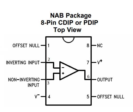
Pin Configuration of LM741
|
PIN NO. |
PIN Description |
|
1 |
Offset null |
|
2 |
Inverting (-) input terminal |
|
3 |
non-inverting (+) input terminal |
|
4 |
negative voltage supply (-VCC) |
|
5 |
offset null |
|
6 |
Output voltage pin |
|
7 |
positive voltage supply (+VCC) |
|
8 |
not connected |
Testing the Howland Current Pump Hardware
According to ohm’s law, increasing the value of load resistance will also change the voltage across it. But an ideal source should maintain constant amount of current flowing through the load resistance. Below is the hardware setup to test the Howland current pump circuit, here the 9v power supply is given through a RPS (Regulated Power Supply) but a 9v battery can also be used for testing. Here, we have tested the circuit with a load resistance of 2k and 3.9k, and measured the current across the load using a digital multi-meter. As shown in below images the current remains constant in both the conditions.


The resistor can also be replaced with some active load like motor or LED. Complete demonstration video of the Howland Current Pump is given below.
Application of Howland Current Pump
Below are some applications for the Howland Current Pump:
- Testing other devices
- Experimenting
- Production test
- Biasing diodes and transistors
- For setting test conditions
