Today we will learn about Kirchhoff’s Circuit Law. Before going into detail and its theory part, let’s see what actually it is.
In 1845, German physicist Gustav Kirchhoff was described relationship of two quantities in Current and potential difference (Voltage) inside a circuit. This relationship or rule is called as Kirchhoff’s circuit Law.
Kirchhoff’s Circuit Law consist two laws, Kirchhoff’s current law - which is related with current flowing, inside a closed circuit and called as KCL and the other one is Kirchhoff’s voltage law which is to deal with the voltage sources of the circuit, known as Kirchhoff’s voltage law or KVL.
Kirchhoff’s First Law/ KCL
Kirchhoff’s first law is “At any node (junction) in an electrical circuit, the sum of currents flowing into that node is equal to the sum of currents flowing out of that node.” That means, if we consider a node as a water tank, the water flow speed, which is filling the tank is equal to the one which is empting it.
So, in case of electricity, the sum of currents entering in the node is equal to the sum of exiting the node.
We will better understand this in the next image.

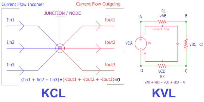
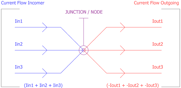
In this diagram, there is a junction where multiple wires are connected together. Blue wires are sourcing or supplying the current in the node and the red wires are sinking currents from the node. The three incomers are respectively Iin1, Iin2 and Iin3 and the other outgoing sinkers are respectively Iout1, Iout2, and Iout3.
As per the law, the total incoming current at this node is equal to the sum of three wire’s current (which is Iin1 + Iin2 + Iin3), and also it is equal to the sum of three outgoing wire’s current ( Iout1 + Iout2 + Iout3).
So,
(Iin1 + Iin2 + Iin3) + (-Iout1 + -Iout2 + -Iout3) = 0.
Kirchhoff’s second Law/ KVL
Kirchhoff’s second law concept is also very useful for circuit analysis. In his Second law, it is stated that “For a closed loop series network or path, the algebraic sum of the products of resistances of the conductors and the current in them, is equal to zero or the total EMF available in that loop”.
The directed sum of the potential differences or voltage across all resistance (conductor’s resistance in case of no existence of other resistive products) is equal to Zero, 0.
Let’s see the diagram.

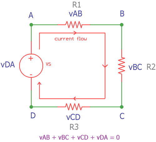
In this diagram, 4 resistors connected across a supply source “vs”. The current is flowing inside the closed network from positive node to the negative node, through the resistors in clockwise direction. As per the ohm’s law in DC circuit Theory, across each resistor, there will be some voltage loss due to the relationship of resistance and current. If we look at the formula, it is V = IR, where I is the current flow through the resistor. In this network, there are four points across each resistors, First point is A which is sourcing the current from the voltage source and supplying the current to the R1. Same thing happens for the B, C and D.
As per the law of KCL, the nodes A, B, C, D where the current is entering and the current is outgoing are the same. At those nodes the sum of incoming and outgoing current is equal to 0, as the nodes are common between sinking and sourcing current.
Now, the Voltage drop across A and B is vAB, B and C is vBC, C and D is vCD , D and A is vDA.
The sum of those three potential differences is vAB + vBC + vCD, and the potential difference between the voltage source (between D and A) is –vDA. Due to the clockwise current flow, the voltage source is reversed, and due to that reason it is negative in value.
Therefore, the sum of total potential differences is
vAB + vBC + vCD + (-vDA) = 0
One thing we should keep in mind that the current flow should be in clockwise in every node and resistance path, otherwise the calculation will not be accurate.
Common Terminology in DC Circuit Theory:
We are now already familiar with Kirchhoff’s circuit law about voltage and current, KCL and KVL, but as we already seen in previous tutorial that using ohm’s law, we can measure currents and voltage across a resistor. But, in case of complex circuit like bridge and network, calculating the current flow and voltage drop is become more complex using only ohm’s law. In those cases, Kirchhoff’s law is very useful to obtain perfect results.
In the case of analysis, few terms are used for describing the parts of the circuitry. These terms are as follows:-
Series:-
When the same amount of current is flowing through the all components, connected in one by one at the end is called series connection
Parallel:-
When the same amount of voltage is applied across all components, connected parallel where both the ends of all the components are connected at two points, in a combination of one is to one which is in same potential difference.
Branch:-
Single or multiple components are connected between two nodes. That can be resistive components or voltage supply sources, is called as branch.
Circuitry / circuit:-
Closed loop with conducting path(s) in which current flows.
Loop:-
Closed path in a circuit in which no node or junction is encountered more than once.
Mesh:-
Single open loop with no closed path and no components are inside it.
Node:-
It is a connection or terminal within a circuit, where two or more elements are electrically connected and providing two or more branches. In schematic, it is a dot where minimum two connections are made.
Junction:-
Junction is the synonym of Node.
Path:-
Connecting elements or supply sources in single line.
Example to solve Circuit using KCL and KVL:

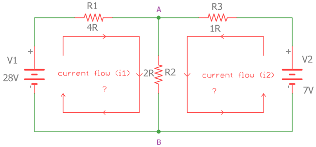
Here is a two loop circuit. In the first loop, V1 is the voltage source which is supplying 28V across R1 and R2 and in the second loop; V2 is the voltage source providing 7V across R3 and R2. Here are two different voltage sources, providing different voltages across two loop paths. The resistor R2 is common in both cases. We need to calculate two current flows, i1 and i2 using the KCL and KVL formula and also apply ohm’s law when needed.
Let’s calculate for the first loop.
As described before in the KVL, that in a closed loop series network path, the potential difference of all resistors are equal to 0.
That means the potential difference across R1, R2 and V1 in case of clockwise current flow is equal to zero.
VR1 + VR2 + (-V1) = 0
Let’s find out the potential difference across the resistors.
In case of VR1
As per the ohms law V = IR (I = current and R = Resistance in ohms)
VR1 = (i1) x 4
VR1 = 4 (i1)
In case of VR2
R2 is common for both loops. So the total current flowing across this resistor is the sum of both currents, thus I across R2 is (i1 + i2).
So,
As per the ohms law V = IR (I = current and R = Resistance in ohms)
VR2 = (i1 + i2) x 2
VR1 = 2 {(i1) + (i2)}
In case of V1,
As the current is flowing clockwise direction the potential difference will be negative, so it is -28V.
Thus, as per KVL
VR1 + VR2 + (-V1) = 0
VR1 + VR2 + (-V1) = 0
4 (i1) + 2 {(i1) + (i2)} - 28 =
4 (i1) + 2 (i1) + 2 (i2) – 28 = 0
6 (il) + 2 (i2) = 28 …………………….. Equation 1
Let’s calculate the second loop.
In this case the current is flowing in anticlockwise direction.
Same as the previous one, the potential difference across R3, R2 and V2 in case of clockwise current flow is equal to zero.
VR3 + VR2 + V1 = 0
Let’s find out the potential difference across these resistors.
In case of VR3
It will be negative due to anticlockwise direction.
VR3 = -(i2) x 1
VR3 = -1 (i2)
In case of VR2,
It will also be negative due to anticlockwise direction,
R2 is common for both loops. So the total current flowing across this resistor is the sum of both currents, thus I across R2 is (i1 + i2).
As per the ohms law V = IR (I = current and R = Resistance in ohms)

VR2 = -(i1 + i2) x 2
VR2 = -2 {(i1) + (i2)}
In case of V2
As the current is flowing anticlockwise the potential difference will be positive, exactly reverse of the V1, so it is 7V.
So, as per KVL
VR3 + VR2 + V2 = 0
VR3 + VR2 + V2 = 0
-1 (i2) - 2 {(i1) + (i2)} + 7 = 0
-1 (i2) - 2 (i1) - 2 (i2) + 7 = 0
-2 (il) - 3 (i2) = -7 …………………….. Equation 2
Now solving those two Simultaneous equations, we get i1 is 5A and i2 is -1 A.
Now, we will calculate the value of current flowing through the resistor R2.
As it is the sharing resistor for both loops it is difficult to obtain the result by using only ohm’s law.
As per the rule of KCL, the current entering in the node is equal to current exiting in the node.
So in case of the current flow through the resistor R2:-
iR2 = i1 + i2
= 5A + (-1A)
= 4A
The current flowing through this resistor R2 is 4A.
This is how KCL and KVL are useful to determine the current and voltage in complex circuitry.
Steps to Apply Kirchhoff’s law in Circuits:
- Labeling all voltage source and resistances as V1, V2, R1, R2 etc, if the values are assumable then the assumptions are needed.
- Labeling each branch or loop current as i1, i2, i3 etc
- Applying Kirchhoff’s voltage law (KVL) for each respective node.
- Applying Kirchhoff’s current law (KCL) for each individual, independent loop in the circuit.
- Linear simultaneous equations will be applicable when needed, to know the unknown values.


