
Measuring current is a simple task – all you need to do is hook up a multimeter to the circuit you want to measure and the meter gives you a clean value to use. Sometimes you can’t really ‘open up’ the circuit to put a multimeter in series with what you want to measure. This is solved quite simply too – you just need to measure the voltage across a known resistance in the circuit – the current then is simply the voltage divided by the resistance (from Ohm’s law).
Things get a little complicated when you want to measure changing signals. This is at the mercy of the refresh rate (number of samples per second) of the multimeter, and the average human can comprehend only so many changes to a display per second. Measuring AC becomes a little simpler if your multimeter has an RMS voltage measurement (RMS voltage is the voltage of an AC signal that would transmit the same amount of power that a DC supply of that voltage would produce). This is strictly limited to periodic signals (square waves and the like are strictly out of question unless the RMS measure is ‘true’, even then, there are no guarantees on the accuracy of the measurement). Most multimeters are also low pass filtered, which prevents AC measurement above a few hundred Hertz.
How to use Oscilloscope to Measure Current
The oscilloscope fills in the gap between human perception and the steady values of a multimeter – it displays a sort of voltage-time ‘graph’ of a signal, which allows a better visualization of changing signals compared to a set of changing numbers on a multimeter.
Measuring signals with frequencies up to several gigahertz is also possible, given the right equipment. However, the oscilloscope is a high impedance voltage measuring device – it cannot measure currents as such. Using an oscilloscope to measure currents requires converting a current to a voltage, and this can be done a few ways.
1. Using a Shunt Resistor
This is perhaps the simplest way to measure current, and will be discussed here in detail.
The current-to-voltage converter here is the humble resistor.
Basic knowledge tells us that the voltage across a resistor is proportional to the current flowing through it. This can be summed up by Ohm’s law:
V = IR
Where V is the voltage across the resistor, I is the current through the resistor and R is the resistance of the resistor, all in their respective units.
The trick here is to use a resistor value that does not affect the overall circuit being measured, since the voltage drop across the shunt resistor causes less voltage to be dropped across the circuit it is placed in. A general rule of thumb would be to use a resistor that is much smaller than the resistance/impedance of the circuit being measured (ten times less in a good starting point) to prevent the current in the circuit being measured from being influenced by the shunt.
For example, the transformer and MOSFET in a DC-DC converter might have a total (DC) resistance of tens of milliohms, placing a large (say) 1Ω resistor would result in most of the voltage being dropped across the shunt (remember that for resistors in series, the ratio of voltage dropped across the resistors is the ratio of their resistances) and hence a greater power loss. The resistor just converts the current to a voltage for measurement, so the power does no useful work. At the same time, a small resistor (1mΩ) would drop only a small (but measurable) voltage across it, leaving the rest of the voltage to do useful work.
Now, having selected a resistor value, you can connect the probe ground to circuit ground and the probe tip to the shunt resistance, as shown in the figure below.


There are a few neat tricks you can use here.
Supposing your shunt has a resistance of 100mΩ, then a current of 1A would result in a voltage drop of 100mV, giving us a ‘sensitivity’ of 100mV per amp. This should cause no problems if you’re careful, but many times the 100mV is taken literally – in other words, confused with 100mA.
This problem can be overcome by setting your input setting to 100X – the probe is already 10X attenuating, so adding another 10X to the signal brings it right back to 1V per amp, i.e. the input is ‘multiplied’ by 10. Most oscilloscopes come with this feature of being able to select the input attenuation. However, there may be scopes that support only 1X and 10X.
Another useful little feature is being able to set the vertical units being displayed on screen – the V can be changed to A, W and U, among others.
Things get complicated when you can’t place the shunt low side. The scope ground is directly connected to earth ground, so assuming your power supply is also grounded, connecting the probe ground clip to any random point in the circuit will short that point to ground.
This can be prevented by doing something called a differential measurement.
Most oscilloscopes have a math function, which can be used to perform mathematical operations on the displayed waveform(s). Note that this does not change the actual signal in any way!
The function we’ll be using here is the subtract function, which displays the difference of two selected waveforms.
Since voltage is simply the potential difference across two points, we can hook one probe to each point and connect the ground clips to circuit ground as shown in the figure.

By displaying the difference between the two signals we can determine the current.
The same ‘attenuation’ trick used above applies here too, just remember to change both channels.
Disadvantages of using shunt resistor:
There are a few disadvantages to using shunt resistor. The first is the tolerance, which may be as bad as 5%. This is something that has to be accounted for with some difficulty.
The second is the temperature coefficient. The resistance of resistors increases with temperature, which results in a larger voltage drop for a given current. This is particularly bad with high current shunt resistors.
2. Using a Current Probe
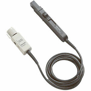
Readymade current probes (called ‘current clamps’; they clamp on to wires without interrupting circuits) are available in the market, but you don’t see many hobbyists using them because of their prohibitive cost.
These probes use one of two methods.
The first method is the use of a coil wound around a semi-circular ferrite core. The current in the wire, the probe has been clamped around, generates a magnetic field in the ferrite. This in turn induces a voltage in the coil. The voltage is proportional to the rate of change of current. An integrator ‘integrates’ the waveform and produces an output that is proportional to the current. The output scale is typically between 1mV and 1V per amp.
The second method uses a Hall sensor sandwiched between two ferrite semicircles. The Hall sensor produces a voltage that is proportional to the current.
3. A Quick-and-Dirty Method
This method requires no extra components other than a scope and a probe.
This method is much like using a current probe. Loop the probe ground wire around the wire carrying the current to be measured and then connect the ground clip to the probe tip.

The voltage produced is again proportional to the rate of change of current, and you need to perform some math on the waveform (namely integration; most scopes have this under the ‘math’ menu) in order interpret it as a current.
Electrically speaking, the shorted probe basically forms a wire loop that acts somewhat like a current transformer, as shown in the figure.

Conclusion
There are several methods to measure changing current waveforms using an oscilloscope. The simplest one is using a current shunt and measuring the voltage across it.
