The LA4440 is a very popular dual-channel audio amplifier commonly used to build high power audio amplifiers. The IC is known for its high power, easy availability and cheap price which makes it popular among
Home Theatre and Car Amplifier Systems which operate on 12V. Hence in this article, we will learn how to build a High-Power Stereo Audio Amplifier using the LS4440 Audio Amplifier IC. The circuit will have two LS4440 amplifiers ICs and will be able to drive two 20W Speakers (20W+20W) with volume, bass and treble control. Also, the audio input for our amplifier board can either be provided directly from an audio jack or wirelessly using Bluetooth.
We have previously built a lot of Audio Amplifier circuits ranging from small 10W amplifiers to heavy 100W Power amplifier using different classes of the Power amplifier to suit various applications. You can also check them out if your requirement is different.
LA4440 IC
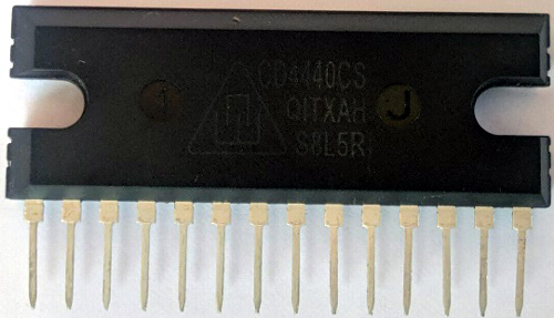
Before starting to build this amplifier, let's understand more about the LA4440 Power Amplifier IC to know about its technical specifications so that we can design our amplifier efficiently. As shown below the LA4440 is a 14-pin Linear Audio Amplifier IC developed by SANYO.
The IC can be used as a mono audio amplifier or as a stereo dual-channel audio amplifier. It has dual enabling modes, namely the stereo mode, and bridge mode. The main difference between those two modes of configuration is in stereo mode a single IC can drive a maximum of 6W + 6W two speakers that mean only 12 watts of load but in the bridge mode configuration, you will get 19W audio output from a single IC for a single speaker. Therefore, we need 2 ICs for making stereo and 2 copies of the same circuit which we will discuss in the circuit diagram section. Here, I configured the audio amplifier in bridge mode for getting 20 W + 20W powerful audio output. Since our design has two ICs it is also referred to as 4440 Double IC Amplifier Circuit. Apart from this our Audio Amplifier IC also has the following advantages.
- It has Good Ripple Rejection 46db
- Good channel separation
- Small Residual noise
- Low audio restoration over a wide range of low frequency to a high frequency of the music.
- Small pop up or starting noise
- Build-in Audio Muting function
- Build-in protection: Over-voltage protection, surge voltage protection, pin-to-pin short protection.
- Minimum spare parts required
What is Ripple Rejection and Why is it Important?
Ripple is the variation of the voltage and current over a steady-state value which can be changed with the load, this causes the noise at the output end of the circuit and thereby lead to distortions. To overcome this problem, a filter is employed which helps in rejecting this noise/ripple. It is called ripple rejection. The LA4440 IC provides a good ripple rejection value of 46dB.
What is Channel Separation?
When a single IC package contains more operational amplifiers (LA4440 IC has 2 channels), one operational amplifier affects the performance of another operational amplifier. To prevent this problem the LA4440 IC provides a good channel separation
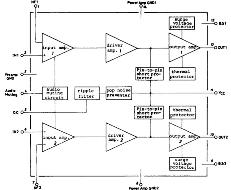
More technical details along with performance graphs can be found in the Datasheet of LA4440 IC. The internal block diagram and pinout image is shown below
Materials Required for 40W Dual IC Stereo Audio Amplifier
The Complete Stereo Audio Amplifier Bill of Materials is listed below. Most of the components used should be available easily since they are commonly used in audio amplifier circuits.
| S.No | Parts | Type | Quantity |
| 1 | LA4440 | IC (SANYO) | 2 |
| 2 | 2200uF/ 50 V | CAPACITOR (KELTRON) | 2 |
| 3 | 47uF/ 25 v | CAPACITOR (KELTRON) | 4 |
| 4 | 470uF / 25 V | CAPACITOR (KELTRON) | 4 |
| 5 | 100uF/ 25 V | CAPACITOR (KELTRON) | 2 |
| 6 | 1uF/ 25V | CAPACITOR (KELTRON) | 2 |
| 7 | 104 PF | CAPACITOR (KELTRON) | 8 |
| 8 | 220 OHOMS | RESISTOR | 2 |
| 9 | 1 K | RESISTOR | 2 |
| 10 | 2.2 K | RESISTOR | 2 |
| 11 | DUAL CHANNEL 50K POTENTIOMETER | BOURNS / LRM | 3 |
| 12 | 2 PIN SCREW TERMINAL | GENERIC | 3 |
| 13 | 3 PIN SCREW TERMINAL | GENERIC | 1 |
| 14 | LM7805 | VOLTAGE REGULETOR IC | 1 |
| 15 | BLUETOOTH MODULE | COSMIC | 1 |
| 16 | TRANSFORMER | 0 -12 V ( CLASSIC) | 1 |
| 17 | SPEAKER (20W) 4 ohms | (SWETON) | 2 |
| 18 | 1N5408 | 3A General purpose Diod | 4 |
| 19 | Heat sink | Use Aluminium Heatsink plate | 1 |
| 20 | Cooling fan | Computer cabinet cooling fan | 1 |
| 21 | Some jumper wire |
LA4440 Double IC Amplifier Circuit
The complete 4440IC Amplifier circuit diagram is shown in the image below. Because of the high-power nature of the circuit, it is not recommended to used a breadboard to build this circuit. Hence, we will be building a PCB at home by designing an Audio Amplifier PCB for this circuit.

I have connected the capacitors C13 and C14 on the first IC and in the same manner C23, and C16 for the second IC, to the IC pins 1 and 7. These capacitors are called feedback capacitors. The low cut-off frequency of our amplifier depends on the value of these capacitors if the value is increased the starting time will be delayed. The voltage gain of these capacitors on IC 1 and 2 can be adjusted by varying the value of Resistor R1 and R2 respectively.
The Capacitors C15 and C19 for the first IC and C20 and C21 for the second IC are connected with of output terminal with IC Pins 9 to 10 and 13 to 12. These capacitors are called Bootstrap Capacitors and are used for Bass or low-frequency adjusting.
The C3 and C4 are very important capacitors. The value of this capacitor should be high, normally 2200uF 35V or 4700uF 35v is recommended for main power supply filtration and load handling. The capacitors are rated for 1Amp to 3Amp to improve the sound quality. The Capacitor C2 and C5 are Filter capacitors that are used to filter the audio input provided to our Amplifier IC.
The capacitors C18 and C17 are the bypass capacitors that are used in an audio system or other electronic circuits for noise filtration. When an active device like our audio amplifier is connected to the power supply, the current drawn by our device will create a voltage drop across the power supply. Due to the change in impedance of our load and several active loads connected on the same path the current drawn will fluctuate and produce more voltage spikes and ground bounce. To avoid this problem, we normally use a bypass capacitor in our load that provides a bypass path for transient current instead of flowing through the common path.
LA4440 Audio Amplifier PCB Design
As mentioned earlier the circuit involves a high current path and hence cannot be built and tested on a breadboard. Hence, we have designed a PCB for the above circuit using the Eagle Software. You can use any PCB design software of your choice. Also, you can solder the circuit directly on a perf board if you do not want to design a PCB. My PCB Layout looks like this as shown below.
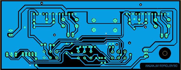
We will be using this PCB design layout to build our own PCB at the home. You can also download the GERBER file for this PCB from the link below. Once you get the GERBER file you can either create the PCB in the home by following the Homemade PCB instructions or share the GERBER file with a PCB manufacturer to get them fabricated.
Download LA4440 High Power Stereo Audio Amplifier PCB GERBER
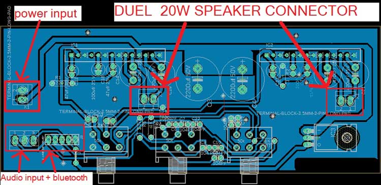
The PCB design has two Audio inputs, one is through direct audio line via aux and 3.5mm Audio jack and the other is for wireless Bluetooth connection. We have also used screw terminals to power the board and connect two 20W speakers. The potentiometers are used to control volume, bass, and treble.
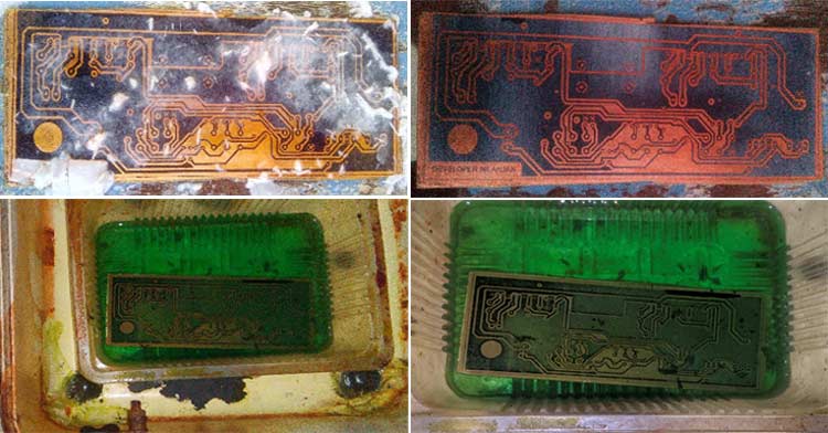
Building PCB Using Toner Transfer Method
For the demonstration of this project, we have created our own PCB using the Toner transfer method. The below images show the various stages of our board during the fabrication process.
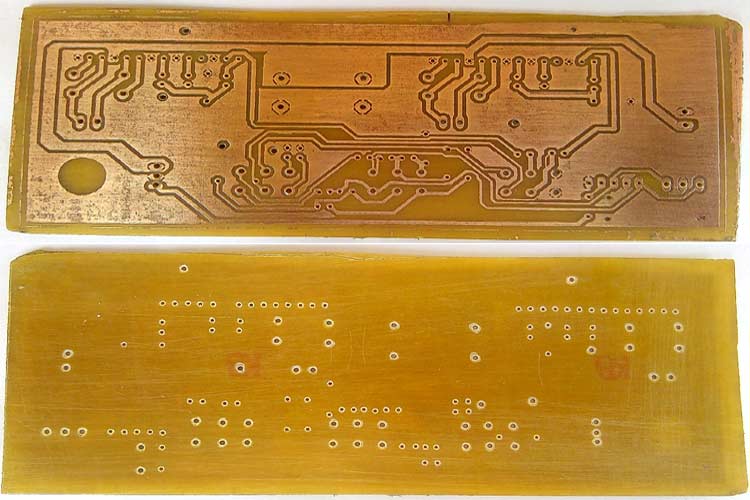
Check out the image given below to see how the homemade PCB looks like after drilling all the component pads. As you can see the board has turned out and neat and the pads are all distinct and clear.
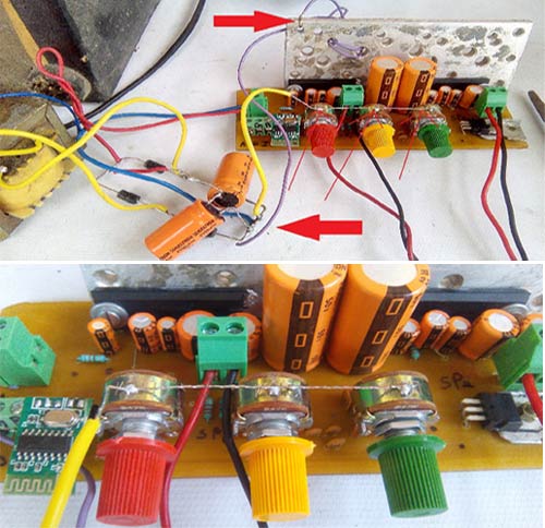
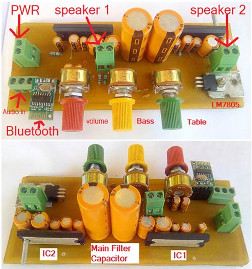
Once the board is read, it’s time to insert all the components and solder it on the custom-made PCB. The components that I used to solder the board are shown below. Here, I am using a dual-channel potentiometer for controlling volume, bass, treble. For the power supply, you can use 12v 1 Amp to 3 Amp of power supply or 12V battery.
The two-pin screw terminals are used to power the power and connect the speakers. The three-pin screw terminals are used to provide audio input. We are also adding a mini onboard Bluetooth module because nowadays people like to play songs directly from their mobile phones and obviously through wireless connectivity. You also need to insert a male-female header for easily removing and changing it. For the power supply of this Bluetooth module, I have used an LM7805 Positive voltage Regulator IC which helps to control and drop the voltage from 12 V to 5V.

Note that I had to remove the Diode bridge part from the PCB to reduce the circuit size with the lesser dimension and to make it compact. But for the transformer power supply, you need to take a Diode bridge with 4 pieces of 5408 general purpose 3 Amp Diode before giving input to this amplifier circuit. The image given below shows how it appears after all the components have been soldered.
LA440 Amplifier Circuit Working
Once the board is ready, we can test it by directly connecting the speakers and powering it. The Audio input can either be from 3.5mm audio jack (three-pin screw terminal) or through our Bluetooth module. The complete working of the Amplifier circuit is demonstrated in both the mode in the video below. If you have any questions, you can use our Circuitdigest forum to post your questions.
Audio Amplifier Design Tips and Considerations
The LA4440 or CD4440 IC has an inbuilt thermal shutdown and it dissipates a lot of heat. So attach a good heat sink for the extended life. Also, you can attach a cooling fan to your amplifier cabinet. It is a common issue that the Amplifier might suffer from noise and produce a humming sound. To avoid the audio amplifier noise problem, make sure the following is checked.
- The Heat sink is in common GND with the power supply negative terminals.
- Use a couple of big capacitors at power filter and rectification stages like 2200uF, 4700uF or 6800uF or 10000uF 25v or 50V capacitor for best result. Don’t use a transformer power supply as it is not needed for power from the battery.
- The volume, bass, treble potentiometer body should be common ground with power supply negative.
- Use a metallic case/cabinet
- Also, noise depends on good Earthing of the mainline and should be connected with the cabinet.
- You can also use an Audio Transformer for isolation and noise filtering.