
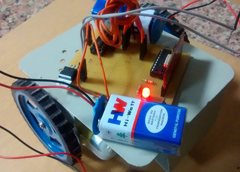
In present time almost all the people are familiar with robots. Robots play a very important role in human life. Robots are a machine which reduces the human efforts in heavy works in industries, building etc. and makes life easy. In Our previous Projects we have made some robots like line follower, DTMF controlled robot, gesture controlled robot, computer controlled robot, but in this tutorial we are going to design a very interesting robot, that is RF controlled Robot. Interesting thing in this project is that it will run without using any microcontroller. Here we will run it directly by RF Decoder and Motor Driver.
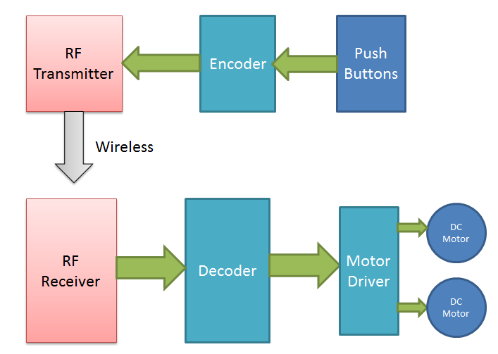
RF controlled robot is controlled by using Four push button placed at transmitter side. Here we only need to push the buttons to control the robot. A transmitting device is used in your hand which also contains a RF Transmitter and a RF Encoder. This transmitter part will transmit command to robot so that it can do the required task like moving forward, reverse, turning left, turning right and stop. All these tasks will perform by using four push buttons that are placed on RF transmitter.
Required Components
- DC Motor - 2
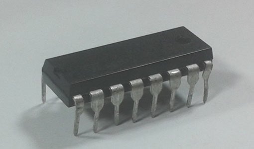
- HT12D - 1
- HT12E - 1
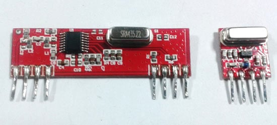
- RF Pair - 1
- Motor Driver L293D - 1
- 9 Volt Battery - 3
- Battery Connector - 3
- Connecting wires
- Robot Chasis - 1
- 7805 - 2
- 750K resistor - 1
- 33K resistor - 1
- 1K Resistor - 1
- PCB
L293D Motor Driver
L293D is a motor driver IC which has two channels for driving two motors. L293D has Two inbuilt Transistor Darlington pair for current amplification and an separate power supply pin for giving external supply for motors.
RF Transmitter and Receiver
This is a ASK Hybrid Transmitter and receiver module operates at 433Mhz frequency. This module has a crystal stabilized oscillator for maintain accurate frequency control for best range. There we have to need only one antenna externally for this module.
RF Transmitter Features:
- Frequency Range: 433 Mhz
- Output Power: 4-16dBm
- Input supply: 3 to 12 volt dc
RF Receiver Features:
- Sensitivity: -105dBm
- IF Frequency : 1MHz
- Low Power Consumption
- Current 3.5 mA
- Supply voltage: 5 volt
This Module is very cost efficient where long range RF communication is required. This module does not send data using UART communication of PC or microcontroller directly because there is lots of noise at this frequency and its Analog technology. We can use this module with the help of encoder and decoder ICs which extract data from the noise.
The range of transmitter is about 100 meters at maximum supply voltage and for 5 volt the range of transmitter is about 50-60 meter with using a simple wire of single code 17cm length antenna.
Pin Description of RF Tx
- GND - Ground supply
- Data In - This pin accept serial data from encoder
- Vcc - +5 Volt should be connect to this pin
- Antenna - A wrapped connect to this pin for proper transmission of data
Pin Description of RF Rx
- GND - Ground
- Data In - This pin give output serial data to Decoder
- Data In - This pin give output serial data to Decoder
- Vcc - +5 Volt should be connect to this pin
- Vcc - +5 Volt should be connect to this pin
- GND - Ground
- GND - Ground
- Antenna - A wrapped connect to this pin for proper Reception of data
Circuit Diagrams and Explanation
Circuit Diagram for RF Transmitter:

Circuit Diagram for RF Receiver:

As shown in above figures, circuit diagrams for RF controlled robot are quite simple where a RF pair is used for communication. Connections for transmitter and receiver show in circuit diagrams. Two 9 volt batteries are used to power the motor driver and remaining Rx Circuit. And another 9 Volt battery is used to power the transmitter.
RF Controlled Robot has two main parts namely:
- Transmitter part
- Receiver part
[Also check: RF Transmitter and Receiver Circuit]
In transmitter part a data Encoder and a RF transmitter is used. As we have already mentioned above that we are using four push buttons to run the robot, these four buttons are connected with Encoder with respect to ground. When we will press any button encoder will get a digital LOW signal and then applied this signal serially to RF transmitter. The Encoder IC HT12E encodes data or signal or converting it into serial form and then sends this signal by using RF transmitter into the environment.
At the receiver end we have used RF receiver to receive data or signal and then applied to HT12D decoder. This decoder IC converts the received serial data to parallel and then send these decoded signal to L293D Motor driver IC. According to the received data robot runs by using two dc motor in forward, reverse, left, right and stop direction.
Working of RF Controlled Robot:
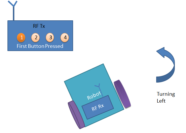
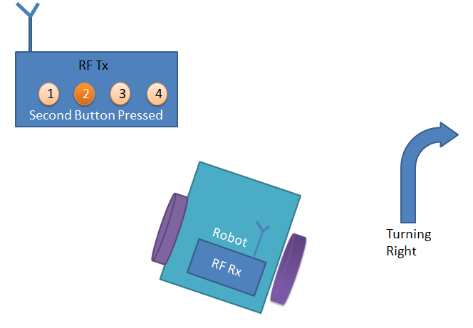
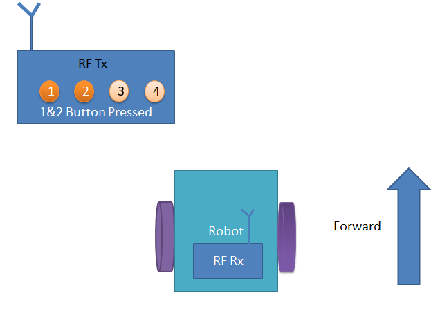
RF controlled robot move according to button pressed at Transmitter.
|
Button Pressed at Transmitter |
Moving Direction of Robot |
|
First (1) |
Left |
|
Second (2) |
Right |
|
First and Second (1 & 2) |
Forward |
|
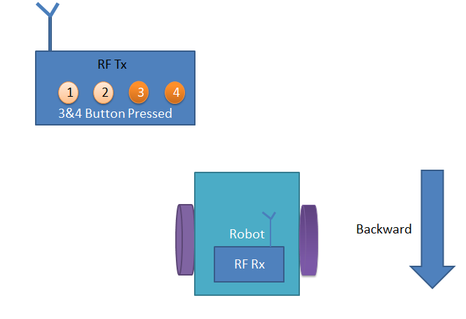
Third and Fourth (3 & 4) |
Backward |
|
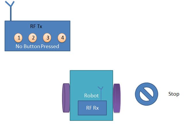
No Button Pressed |
Stop |
When we press first button (1 mention on circuit and hardware) robot start to moving left side and moving continues until the button is released.
When we press second button at transmitter, robot start moving in right side until button is released.
When we press first and second button at the same time, Robot start moving in forward direction until push buttons are released.
When we press third and fourth button at the same time, robot start moving in backward direction and keep going until push buttons are released.
And when no push Button is pressed, robot stops.
Comments
You can check the Circuit
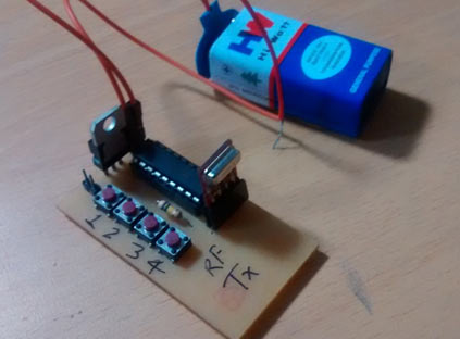
You can check the Circuit Diagram for RF Transmitter above and connect RF Tx module to HT12E along with Push buttons. You can assemble the whole Transmitter circuit on PCB. Check here for making PCB
This is a RF Robot without
This is a RF Robot without any microcontroller, so since we haven't used any microcontroller, we don't need any program code.
Working Fine
I have made this one and it worked perfect but there is a problem, if try to used any other power source other than 9v battery, motor on switch s4.2 and s4.3 starts misbehaving such as after leaving the switch it keeps on running, so i have to turn off the power and on again.
Any suggestions ??
What power source are you
What power source are you using? Also check you circuit connections.
M1 and M2 are the two DC
M1 and M2 are the two DC motors to rotate the wheels of Robot.
Can any advancement done in
Can any advancement done in this circuit ??
If so what kind ?
sir ,i need the pcb layout
sir ,i need the pcb layout of TXR section,will u plz help me
There are so many softwares
There are so many softwares are available for Schematic to PCB layout conversion like Easy EDA, Fritzing etc.
not working
My ckt is not working.
What kind of motors are that
Is it dc brush motors
They are DC motors, we have
They are DC motors, we have used L293D for motor Driver Circuit many times. please check this link and learn: http://circuitdigest.com/search/node/l293d%20driver
i have four pin receiver.how
i have four pin receiver.how to connect. can u upload the schematic for 4 pin
With 3-pin RF transmitter and
With 3-pin RF transmitter and receiver modules, you don't need to connect Encoder & decoder and circuit will be changed accordingly. Check this Article https://www(dot)elprocus(dot)com/rf-module-transmitter-receiver/ for understand the connections.
rf based remote controlled car
what are the main applications of rf based remote controlled car?
Yes you can connect 4 DC
Yes you can connect 4 DC motors to L293D, but then you need more power to drive all the motors. Check this Robot where we have used 4 motors with powerfully battery: DIY Smart Vacuum Cleaning Robot using Arduino
Quick Question
Do the resistors in the receiver circuit limit the amount of current going to the motors. Are the motors getting the full 9 volts of the battery because your car seems quite slow for that amount of voltage.
Please Reply.
No, resistors are not for
No, resistors are not for limiting the current to the Motors. Even we have used Motor Driver IC L293D to drive more current, you can further use more powerful battery (or fresh 9v Batteries) according to the motors.
It is not exactly the robot ,
It is not exactly the robot , it is an radio controled car. To be a robot have to install the firmware...
i want to prepare a helicopter by rf control with High power,
Can i use this instead of the robot...
.. and how to increase the range.... rply me soon
Check Cell Phone Controlled
Check Cell Phone Controlled Robot using 8051 Microcontroller for high range.
mplab program
i want the program for controlling the dc motors using two switches for moving forward and backward by using rf module to pic16f877a.
Range of rf module
What is the range of the rf module that you have used. I all want it be be obstacle avoiding robot. How can i convert it into that.
Better use Ultrasonic or IR
Better use Ultrasonic or IR sensor for obstacle avoiding robot, search on this website for these robots
This article only shows on
This article only shows on how to make RF controlled robot without microcontroller. However, We guys tried to make a Wireless Robot Control Using RF Module where this project aims of a similar wireless remote controlling applicable to two-wheel drive robots. The wireless remote is a 434 RF module and the robot is driven on DC motors controlled by an L293D motor driver IC. Typically, 434 RF modules have a range of 50-60 metre but can be extended up to 300-350 metre. So, after extending the operational range of RF module, the RC robot will have an impressive distance to wander around. Learn more about extending the operational range of RF modules here []
I have made the same but
I have made the same but after leaving the switch it remains turn on.
I have not connected 293. First I am checking only for signal receiving... but signal remains turn on
rc circuit
Wow..i love this rc circuit. Have been looking for this type of circuit that is quite simple for me as a beginner in electronics..
Plz any body tell what is
Plz any body tell what is voltage and rpm value of gear dc motors
Very simple and nice circuit.
Very simple and nice circuit. I done it and it working properly.
Sir where is the 33k resistor
Sir where is the 33k resistor connected to??
rf control robot
sir,we dnt need any program codings & any programs so please give me a link....
sir I arranged the circuit
sir I arranged the circuit step by step on bread board but It doesn't working.. I don't l know where fault is?? shall you help me where frequently faults happen??
My ckt led not working what i
My ckt led not working what i do plz sir help me
selection of resistance
How can choose the resistance for different pair of ics( oscillator resistance)
Plz sir send RF controlled robot curict diagram.
sir ,
i need the RF Controlled robot pcb layout of TX R section,will u plz help me
i need Rx &Tx circuit
i need Rx &Tx circuit diagrams using rf technology and webcam app will you plz help me
plz send both circuit diagrams in to my mail because march 25 is my project external so plz send because my batch mets donot prepare documentation plz help me
hi. I would like to ask if,
hi. I would like to ask if, instead of using dc motor can i used geared motors???
DC (direct current) is the
DC (direct current) is the electrical input to the motor. Gearing only adjusts the output speed and is not directly related to the type of power source.
remot controlled fire fighting robot using rf technology
please send the circuit diagram of remote controlled fire fighting robot using rf technology sourc code

how to connect push buttons to encoder?