
Wireless notice board is very selective term for this project, as it has a very wide scope rather than just being a simple notice board. First we should understand the purpose of this project, in this system we can display a message or notice to some display device like LCD, and this message can be easily set or changed from anywhere in the world, just by using the SMS facility of your mobile handset. Whatever notice we want to display, just send the SMS of that text, with some prefix and suffix.
This is very useful in Hotels, Malls, college, offices and can be used anywhere, even at home. Like you can set the message like “Do not disturb” at your hotel’s room gate, can set message at your home’s door step when you are away, and of course it is used as notice board in schools, colleges, cinema halls etc. And yes, it’s just not a simple Message board, the usefulness of this project is that you can set or change the message or notice from anywhere, just sending SMS from your phone. You can also check a similar project but on a different type of display: Arduino Scoreboard using Outdoor P10 LED Matrix Display.
We have previously used the SMS facility of mobile phone for home security and control the home appliances remotely: PIR Sensor and GSM Based Security System and GSM Based Home Automation using Arduino
Working Explanation:
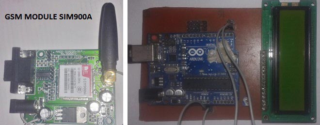
In this project, Arduino UNO is used for controlling the whole process, GSM module (SIM900A) to receive the SMS/message sent from mobile phone and LCD to display the message.
We can send some message or notice like “#Circuit Digest*”, “#We Welcomes You*” through the SMS. Here we have used a prefix in the message string that is ‘#’. This prefix is used to identify the starting of the message or notice. And ‘*’ is used as suffix to indicate the end of the message or notice.
When we send SMS from mobile phone to GSM module then GSM receives that SMS and sends it to Arduino. Now Arduino read this SMS and extract main notice message from the received string and stores in another string. And then sends the extracted message to 16x2 LCD by using appropriate commands.
Further working of this system is explained in the ‘Code Description’ section below. Before we get into programming details we should know about GSM module.
GSM module is used in many communication devices which are based on GSM (Global System for Mobile Communications) technology. It is used to interact with GSM network using a computer. GSM module only understands AT commands, and can respond accordingly. The most basic command is “AT”, if GSM respond OK then it is working good otherwise it respond with “ERROR”. There are various AT commands like ATA for answer a call, ATD to dial a call, AT+CMGR to read the message, AT+CMGS to send the sms etc. AT commands should be followed by Carriage return i.e. \r (0D in hex), like “AT+CMGS\r”. We can use GSM module using these commands:
ATE0 For echo off
AT+CNMI=2,2,0,0,0 <ENTER> Auto opened message Receiving. (No need to open message)
ATD<Mobile Number>; <ENTER> making a call (ATD+919610126059;\r\n)
AT+CMGF=1 <ENTER> Selecting Text mode
AT+CMGS=”Mobile Number” <ENTER> Assigning recipient’s mobile number
>>Now we can write our message
>>After writing message
Ctrl+Z send message command (26 in decimal).
ENTER=0x0d in HEX
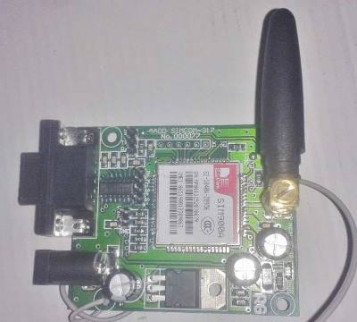
The SIM900 is a complete Quad-band GSM/GPRS Module which delivers GSM/GPRS 850/900/1800/1900MHz performance for voice, SMS and Data with low power consumption.
Circuit Description:
Connections of Wireless Notice Board using GSM and Arduino are simple and shown in the figure below. Here a liquid crystal display (LCD) is used for display the “Notice” or message, which is sent though the mobile phone as SMS. Data pins of LCD namely RS, EN, D4, D5, D6, D7 are connected to arduino digital pin number 7, 6, 5, 4, 3, 2. And Rx and Tx pin of GSM module is directly connected at Tx and Rx pin of Arduino respectively. And GSM module is powered by using a 12 volt adaptor.

Code Description:
The code of the program is easily understandable; the new thing here is GSN initialization function gsm_init(), which is explained in the end.
In the program, first of all we include library for liquid crystal display (LCD) and then we defines data and control pins for LCD and some variables.
#include <LiquidCrystal.h>
LiquidCrystal lcd(7,6,5,4,3,2);

int led=13;

int temp=0,i=0,x=0,k=0;
char str[100],msg[32];
After this, serial communication is initialized at 9600 bps and gives direction to used pin. And initialize GSM Module in setup loop.
void setup()
{
  lcd.begin(16,2);
  Serial.begin(9600);
  pinMode(led, OUTPUT);
  digitalWrite(led, HIGH);
  lcd.print("GSM Initilizing...");
  gsm_init();
  lcd.setCursor(0,0);
  lcd.print("Wireless Notice");
For receiving data serially we use two functions, one is Serial.available which checks any serial data is coming or not and other one is Serial.read which reads the data that comes serially.
void serialEvent()
{
  while(Serial.available())
  {
    char ch=(char)Serial.read();
    str[i++]=ch;
    if(ch == '*')
    {
      temp=1;
      lcd.clear();
      lcd.print("Message Received");
      delay(1000);
    }
  }
}
After receiving data serially, we store it in a string and this string is checked for ‘#’ and ‘*’, to find the starting and ending of the Notice or message. Then finally Notice is printed on LCD using lcd.print:
void loop()
{
  for(unsigned int t=0;t<60000;t++)
  {
    serialEvent();
  if(temp==1)
  {
    x=0,k=0,temp=0;
    while(x<i)
    {
      while(str[x]=='#')
      {
        x++;
        while(str[x]!='*')
        {
          msg[k++]=str[x++];
Initialization function ‘gsm_init()’ for GSM is important here, where firstly, GSM module is checked whether it is connected or not by sending ‘AT’ command to GSM module. If response OK is received, means it is ready. System keeps checking for the module until it becomes ready or until ‘OK’ is received. Then ECHO is turned off by sending the ATE0 command, otherwise GSM module will echo all the commands. Then finally Network availability is checked through the ‘AT+CPIN?’ command, if inserted card is SIM card and PIN is present, it gives the response +CPIN: READY. This is also check repeatedly until the network is found. This can be clearly understood by the Video below.
void gsm_init()
{
  lcd.clear();
  lcd.print("Finding Module..");
  boolean at_flag=1;
  while(at_flag)
  {
    Serial.println("AT");
    while(Serial.available()>0)
    {
      if(Serial.find("OK"))
      at_flag=0;
    }
    delay(1000);
  }
Complete Project Code
#include <LiquidCrystal.h>

LiquidCrystal lcd(7,6,5,4,3,2);
int led=13;
int temp=0,i=0,x=0,k=0;

char str[100],msg[32];
void setup()

{

  lcd.begin(16,2);

  Serial.begin(9600);

  pinMode(led, OUTPUT);

  digitalWrite(led, HIGH);

  lcd.print("GSM Initilizing...");

  gsm_init();

  lcd.setCursor(0,0);

  lcd.print("Wireless Notice");

  lcd.setCursor(0,1);

  lcd.print("    Board      ");

  delay(2000);

  lcd.clear();

  lcd.print("Circuit Digest");

  delay(1000);

  lcd.setCursor(0,1);

  lcd.print("System Ready");

  Serial.println("AT+CNMI=2,2,0,0,0");

  delay(500);

  Serial.println("AT+CMGF=1");

  delay(1000);

  digitalWrite(led, LOW);

}
void loop()

{

  for(unsigned int t=0;t<60000;t++)

  {

    serialEvent();

  if(temp==1)

  {

    x=0,k=0,temp=0;

    while(x<i)

    {

      while(str[x]=='#')

      {

        x++;

        while(str[x]!='*')

        {

          msg[k++]=str[x++];

        }

      }

      x++;

    }

    msg[k]='\0';

    lcd.clear();

    lcd.print(msg);

    delay(1000);

    temp=0;

    i=0;

    x=0;

    k=0;

  }

  }

  lcd.scrollDisplayLeft();

}

void serialEvent()

{

  while(Serial.available())

  {

    char ch=(char)Serial.read();

    str[i++]=ch;

    if(ch == '*')

    {

      temp=1;

      lcd.clear();

      lcd.print("Message Received");

      delay(1000);

    }

  }

}

void gsm_init()

{

  lcd.clear();

  lcd.print("Finding Module..");

  boolean at_flag=1;

  while(at_flag)

  {

    Serial.println("AT");

    while(Serial.available()>0)

    {

      if(Serial.find("OK"))

      at_flag=0;

    }

    delay(1000);

  }
  lcd.clear();

  lcd.print("Module Connected..");

  delay(1000);

  lcd.clear();

  lcd.print("Disabling ECHO");

  boolean echo_flag=1;

  while(echo_flag)

  {

    Serial.println("ATE0");

    while(Serial.available()>0)

    {

      if(Serial.find("OK"))

      echo_flag=0;

    }

    delay(1000);

  }
  lcd.clear();

  lcd.print("Echo OFF");

  delay(1000);

  lcd.clear();

  lcd.print("Finding Network..");

  boolean net_flag=1;

  while(net_flag)

  {

    Serial.println("AT+CPIN?");

    while(Serial.available()>0)

    {

      if(Serial.find("+CPIN: READY"))

      net_flag=0;

    }

    delay(1000);

  }

  lcd.clear();

  lcd.print("Network Found..");

  delay(1000);

  lcd.clear();

}
Comments
Message not displaying on LCD
GSM receiving the message and showing on serial monitor but not displaying on LCD . What may be the reason???
Have you fixed your circuit
Have you fixed your circuit in PCB???
Please show me connections clearly for this project
Please show me connections clearly for this project
Check circuit connections and
Check circuit connections and code.
how would i intialise the the
how would i intialise the the gsm module after writing the code in arduino, like how would i write those AT commands in gsm module?and would u mind sharing ur mail id for further communication?
sir.How to Display the
sir.How to Display the message on Led matrix .please tell what I modify in the Program and circuit diagram.
Not able to display message send from mobile on LCD
The above code after some modification is able to receive message and display it on serial monitor but not on LCD display please help me. your email id is not correct.
Not able to display message send from mobile on LCD
I have modified the code attached because initially it wasn’t working.
Still it is not working i.e. the message send through gsm module is not displaying on LCD but it showing on the serial monitor.
Is there any problem in reading data serially and displaying??
According to your code the string is in # and *???
Please help me out….
Resolve the issue.
yes, string is in # and *.
yes, string is in # and *. The code and circuit diagram are correct, please cross check them twice. Check you LCD, whether it is working properly. What are you getting on LCD.
what program do you use to
what program do you use to draw your circuit diagram ?
thank you
Proteus with Arduino Library
Proteus with Arduino Library installed.
can you please help me design
can you please help me design a circuit diagram for an a Wireless Notice Board using Arduino Uno and GSM?
dude hats off to you
I truly appreciate your work, you have really helped me like anything. Thanks for this bro.!!
Wireless notice board
Interesting reading. I want to setup wireless notice board using SMS. Can I just use a tablet to receive TXt's with a sim, instead of a GSM module & just adapt the tablet to read more as a noticeboard ?
You can use Tablet in place
You can use Tablet in place of Mobile Phone.
can i use Bengali language in
can i use Bengali language in LCD display. Please help.
Yes, you can, you need to
Yes, you can, you need to generate hex code for each character in bengali using this online tool.
sir,dont we need to set baud
sir,dont we need to set baud rate to 2400 as SIM900A does not work with 9600 baud rate.
please attach the correct
please attach the correct coding for us pls
Code is tested you may go
Code is tested you may go ahead with the same given on the website....
best of luck
i have used arduino mega 2560
i have used arduino mega 2560 & GSM 800,do i have to change any part of the code as i was not able to display message.
How to display longer messages
Thanks for a brilliant tutorial, nice and easy to follow. Mine does however refuse to display long messages (I would like to display about 30/40 words) but when I try this it either freezes/doesn't display any text at all or reboots by running through the GSM initializing, ECHO off and etc. How do I get it to recieve and display longer messages?
Thanks in advance :)
You can display long messages
You can display long messages by using the given program itself, it is using lcd.scrollDisplayLeft(); function for scrolling the long messages. I think there may be some problem in your hardwares.
ton of Thnanks
I don't know how to Thank you You really made my day...
May you get more & more success.
WIRELESS NOTICE BOARD ARDUINO CODE
the code just jumps to Finding module, and nothing else, may you please send me one that works well.
Did you get the solution for
Did you get the solution for this problem..please tell me solution if u know
i m also getting the same
i m also getting the same problem ,the code just jumps to Finding module, and nothing else, may you please send me one that works well.
It is the problem related to
It is the problem related to GSM Module, try to just connect GSM module and send AT command and then check whether your GSM responds with OK. Use serial monitor to check the response.
hello sir!iam using gsm 800L
hello sir!iam using gsm 800L.everything is ok but msg is not getting receoved and displayed on the lcd.
no its16*2 lcd display,by the
no its16*2 lcd display,by the way iam sir :)
All term has complete & shown
All term has complete & shown in display, but it doesn't work for sending massese. How can i send SMS? and how can it displayed??.........Please help me...............
First learn to interface GSM
First learn to interface GSM with Arduino for properly sending the SMS: check our various projects using GSM and Arduino
Is there a way to extend the
Is there a way to extend the 32 character limit displayed still using the 16x2 lcd?
it worked! i have changed the
it worked! i have changed the pins to pin no 10 and 11 and it worked and a little bit change in the code.
Hey please share the modified
Hey please share the modified code.
how to insert a buzzer to this project
insert a buzzer to this project and this buzzer is on when message is received by the gsm module
problem with module
Sir I have setup all the connections like yours but i only have the problem with the gsm module yhat it indicate "Finding Module.." on LCD display. Please Sir caan you please solve my problem...
Sir, I need to make this one
Sir, I need to make this one with a bigger dispaly.Is it possible??
Thanks a lot
Thanks a lot
But after making all connections I could see only finding module on LCD and could not see any thing further could you help me out
sir I also need to make this
sir I also need to make this one with a bbigger lcd.is it possible?please tell me
Send sent to the sim is not displayed
Hi saddam, Great work. i'm an electronics enthusiast and try to build circuits and write codes. Every thing seems to be gud but the msg sent to the sim is not getting displayed on the screen. Pls suggest what can i do next.
Stray Error
the above code is showing that it has Stray/302 error
Sir , is this code suitable
Sir , is this code suitable for 128x64 LCD???
No, this code is not suitable
No, this code is not suitable for drive 128x64 LCD
How to compile the above
How to compile the above program? and which software?
sir can i use larger display
sir can i use larger display instead of 16*2 lcd
regarding code
code is showing some warnings in gsm_init()
if(Serial.find("OK"))
if(Serial.find("+CPIN: READY"))
Just showing finding GSM
Just showing finding GSM module pls share the proper code
Include passkey as authentication
Is it possible to use a passkey for authentication? if so, can you please show me how?
notice board project
how to do it using microcontroller?and use more than one lcd for example 2lcd
Message not displaying
hey maddy
I have connected and write code on arduino as per this website . after running Lcd MONITER SHOWS"Circuit digest System ready.But when i send messages it shows same. that means message is not displaying ,or it may not receving.Can you help me ? is there anything that i have to modified these code ? hoping a convenient reply from you.
ERROR
Arduino: 1.8.2 (Windows 10), Board: "Arduino/Genuino Uno"
Build options changed, rebuilding all
C:\Users\akash\Documents\Arduino\LCD_test1\LCD_test1.ino: In function 'void gsm_init()':
C:\Users\akash\Documents\Arduino\LCD_test1\LCD_test1.ino:92:26: warning: deprecated conversion from string constant to 'char*' [-Wwrite-strings]
if(Serial.find("OK"))
^
C:\Users\akash\Documents\Arduino\LCD_test1\LCD_test1.ino:109:26: warning: deprecated conversion from string constant to 'char*' [-Wwrite-strings]
if(Serial.find("OK"))
^
C:\Users\akash\Documents\Arduino\LCD_test1\LCD_test1.ino:126:36: warning: deprecated conversion from string constant to 'char*' [-Wwrite-strings]
if(Serial.find("+CPIN: READY"))
^
Sketch uses 4118 bytes (12%) of program storage space. Maximum is 32256 bytes.
Global variables use 608 bytes (29%) of dynamic memory, leaving 1440 bytes for local variables. Maximum is 2048 bytes.
avrdude: stk500_recv(): programmer is not responding
avrdude: stk500_getsync() attempt 1 of 10: not in sync: resp=0x69
avrdude: stk500_recv(): programmer is not responding
avrdude: stk500_getsync() attempt 2 of 10: not in sync: resp=0x69
avrdude: stk500_recv(): programmer is not responding
avrdude: stk500_getsync() attempt 3 of 10: not in sync: resp=0x69
avrdude: stk500_recv(): programmer is not responding
avrdude: stk500_getsync() attempt 4 of 10: not in sync: resp=0x69
avrdude: stk500_recv(): programmer is not responding
avrdude: stk500_getsync() attempt 5 of 10: not in sync: resp=0x69
avrdude: stk500_recv(): programmer is not responding
avrdude: stk500_getsync() attempt 6 of 10: not in sync: resp=0x69
avrdude: stk500_recv(): programmer is not responding
avrdude: stk500_getsync() attempt 7 of 10: not in sync: resp=0x69
Problem uploading to board. See http://www.arduino.cc/en/Guide/Troubleshooting#upload for suggestions.
avrdude: stk500_recv(): programmer is not responding
avrdude: stk500_getsync() attempt 8 of 10: not in sync: resp=0x69
avrdude: stk500_recv(): programmer is not responding
avrdude: stk500_getsync() attempt 9 of 10: not in sync: resp=0x69
avrdude: stk500_recv(): programmer is not responding
avrdude: stk500_getsync() attempt 10 of 10: not in sync: resp=0x69
This report would have more information with
"Show verbose output during compilation"
option enabled in File -> Preferences.
Mini project
Akash i m alsi getting the same , ditto error on compilation , if u have alredy found the solution please send
I am also getting the same
I am also getting the same problem now can u pls help me to fix it.
did u rectified the errors.
did u rectified the errors. if so send the updated code
sir we are unable understand the code
sir hw does the program read the balance in sim, and how to recharge it again, or how to check bal in it
can we contact you sir pls,,we r doing this proj as our final yr project, please help us out
even if you are charging money for its okay, please help us out
if instead of lcd display we
if instead of lcd display we use leds(24x6)
hai sir can you help me how
hai sir can you help me how to do this? because i do this project for final year project
data telecommunication
hello sir, i really adore with your project , may i get help from you because i make this project too as my final year project . Hope can hear from you soon . i do really need your help sir. Please sir
sir i want to know about the
sir i want to know about the code actually i am not getting that whether the message recieved is stored in str[i++] or is it in x or is x and i the same
sir, i am doing this project
sir, i am doing this project as my final project..if sir could help me with exact materials required??
sir when i tried to send a
sir when i tried to send a message from gsm after sending the messge lcd vnot respond
please help meeee!!!!!!!!!!
Screen size necessary?
Can we change the screen size? Which screen size should be take? Can we make messages be fixed.
size of lcd
sir how much size we can increase of lcd kidly reply?
Its upto you. You can even
Its upto you. You can even use a TFT LCD for this
whats the range in km of this
whats the range in km of this wireless notice board
After run this code error
After run this code error showing stray'\302' how to resolve
Project related
Sir, how to use gsm module ??
how to write code for gsm
https://circuitdigest.com
https://circuitdigest.com/microcontroller-projects/call-and-message-usi…
Use this link to get started with GSM modules. Once you do that, you should be able to do this project
How can i contact you
How can i contact you personally ?
Wants to know how to connect led board with aurduino.(but led board is home made by mi connecting all led in series)
how to send command to gsm
i want to send commad to gsm how can i send
not receiving the serial port output on the lcd
The module is working on lcd interface but the message send by the mobile phone is not received and displayed. I used the same code specified. Please help me out of it to get the output
The module is working on lcd
The module is working on lcd interface but the message send by the mobile phone is not received and displayed. I used the same code specified. Please help me out of it to get the output
Did you pair correctly? Make
Did you pair correctly? Make sure the BT module is working and Arduino is getting data from BT module.
wairless controll notice board
some people facing same problem...like me ..display showing nothing just showing Module fund...nothing else.....can you tell me what is the solution for this problem.
sir i need one help..
sir i need one help..
how to print the message in second line...
i will send the message only in first line but not display in second line..
how can resolve it...
You have to set the LCD
You have to set the LCD cursor in 2nd line before you print anything there
i got these errors while compiling . can someone tell how to sol
C:\Users\tumma\Documents\Arduino\notice_board\notice_board.ino: In function 'void gsm_init()':
C:\Users\tumma\Documents\Arduino\notice_board\notice_board.ino:92:26: warning: ISO C++ forbids converting a string constant to 'char*' [-Wwrite-strings]
if(Serial.find("OK"))
^
C:\Users\tumma\Documents\Arduino\notice_board\notice_board.ino:109:26: warning: ISO C++ forbids converting a string constant to 'char*' [-Wwrite-strings]
if(Serial.find("OK"))
^
C:\Users\tumma\Documents\Arduino\notice_board\notice_board.ino:126:36: warning: ISO C++ forbids converting a string constant to 'char*' [-Wwrite-strings]
if(Serial.find("+CPIN: READY"))
^
Sketch uses 4134 bytes (12%) of program storage space. Maximum is 32256 bytes.
Global variables use 614 bytes (29%) of dynamic memory, leaving 1434 bytes for local variables. Maximum is 2048 bytes.
i got these errors while compiling . can someone tell how to solve these errors,
Sir I have setup all the
Sir I have setup all the connections like yours but i only have the problem with the gsm module that it indicate "Finding Network.." on LCD display and it is stuck on that loop nothing happened after. Please Sir can you please solve my problem or assist me in resolving this problem
...

Thanks a ton, this is one of the few examples of RECEIVING a SMS that work, there are zillions of ones for sending but so few like yours