

Styrofoam and polystyrene have been one of the most efficient methods of model making amongst the maker community, thanks to their lightweight, extremely low cost, and the ease with which they can be crafted into some breathtaking pieces of artwork.
But working with Styrofoam often requires a lot of heated element tools that get expensive and become out of reach for a hobbyist. The best option here is to create a heated Styrofoam cutting tool on your own, since most of the tutorials available online follow a methodology of using a fixed power source, they limit the user experience to the length of the wire. Hence, in this tutorial, we will make a portable foam cutting tool using Nichrome wire.
Components Required to build Hot Wire Foam Cutter
- Nichrome Wire
- IRF540N MOSFET
- Heatsink for the IRF540N
- 100KΩ Potentiometer
- 10K Resistor
- 3C 18650 Li-Ion Cell X 2
- 2S 3A Battery Protection BMS
- Toggle Switch
- Female DC Jack
- Epoxy Sheets
- Heat shrinks.
- 2 M5 Screws with nuts.
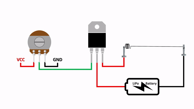
Electric Foam Cutter Parts
The two most important components of the foam cutter are the Nichrome wire and the IRF540N MOSFET.
Nichrome Wire
The heating element used in this project is a Nichrome Wire. “Nichrome” is an alloy made up of mostly Nickle and Chromium with traces of Iron. It is used in almost all heating devices including toasters, room heaters, and electric kettles. We will use a Nichrome wire of around 10 to 15cm in length. This will give us enough temperature to cut the foam also while ensuring that the current draw is limited and within limits of our battery capability.
IRF540 MOSFET
Since we want to efficiently control the current flowing through the wire to control its temperature, we use the IRF540 MOSFET. By controlling the voltage on the Gate terminal of the MOSFET using a potentiometer, we can easily control the current passing through the other two terminals (i.e Source and Drain). More details on the IRF540 MOSFET have been discussed in the schematic discussion of the project. You can also refer to our previous project on Mosfet Switching.
We can visualize the working of the foam cutter components as follows:
Homemade Foam Cutter Circuit Diagram
The complete circuit diagram of the portable DIY Foam Cutter is shown below. The circuit explanation is as follows:

Schematic:
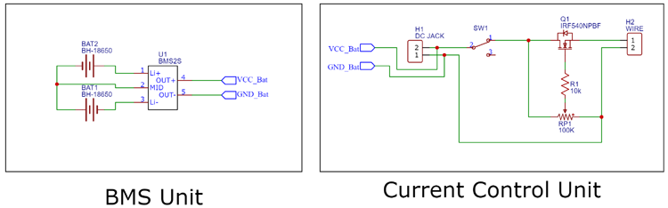
The complete circuit can be divided into two simple parts, these are:
1. Battery Monitoring and Power Unit
This section is responsible for managing the 18650 cells. Since the cells are connected in series, they must be balanced and kept at the same voltages, along with this, there is also a need for limiting the current draw from the cells to prevent overheating of the components.
You can gain a deeper insight into cell balancing and working of BMS from here.
The BMS Module performs all the following functions with ease, the connections can be simply made as:
- Connect the 2 cells in series by joining the positive end of one cell to the negative cell of the other.
- Connect this junction point to the MB terminal on the BMS Module.
- Connect the negative terminal of the first cell to the B- terminal marked on the BMS Module.
- Connect the positive terminal of the second cell to the B+ terminal marked on the BMS Module.
- Connect the P+ and P- Terminals from the BMS Module to the Positive and Negative Terminals on the DC Jack respectively, this will allow us to charge the 18650 cells with an appropriate power supply via the DC Jack.
We can now proceed to connect a switch to the DC Jack positive terminal, this will be our primary switch to control our device.
Also extend a wire from the GND terminal of the DC Jack which can be used to connect the components of the second unit, i.e. the Current Control Unit.
2. Current Control Unit
As the name suggests, this is the section of the circuit that controls the amount of current flowing through the nichrome wire thus controlling the amount of heat generated by the device.
We do so by using the MOSFET IRF540N which is an N channel MOSFET. This MOSFET is a voltage-controlled device that is used to control the flow of current. By Changing the voltage at the GATE Terminal, we can vary the current flowing between the Drain and the Source Terminal.
To control the voltage on the gate terminal of the MOSFET, we simply create a voltage divider circuit using a 100K potentiometer.
Using this voltage divider circuit, we control the current flowing from our battery (connected to the Drain Terminal) to the Load (connected to the Source Terminal).
Making Handheld Hot Wire Foam Cutting Tool
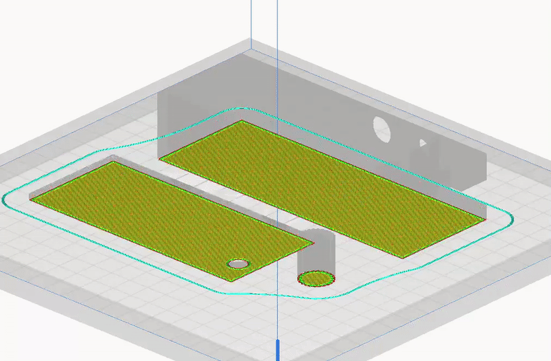
Printing the Case
To house all the electronic components as well as the power source, we will be 3D printing a case, its lid as well as a knob for the potentiometer.
The STL files have been attached to the document, it is recommended to print them with PLA at 20% infill.
You can download STL file from here.
Slicer preview of the 3d files:
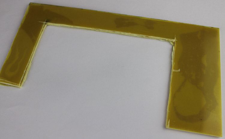
Cutting the Epoxy Sheet
To mount the nichrome wire, we will be using epoxy sheets that will provide us with strength as well as sufficient temperature tolerance.
Cut the epoxy sheet in the following dimensions:
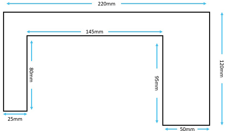
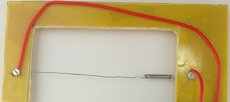
You can now drill mounting holes on both sides to mount the M5 Screws along with your nichrome wire. Remember to add wires to both the terminals of your Nichrome wire. This would look something like this:
Mounting Electronics:
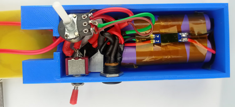
Carefully solder the circuit referring to the schematic and the connection diagram and place all the circuit components inside the 3D printed case.
Final Step:
Simply close the Lid and attach the 3d printed knob to the potentiometer. This completes the project and we can now simply turn the switch on to start cutting Styrofoam.

no, no and no. This isn't a circuit you want to make and use. If you adjust the heat of the wire like this you just waste the energy in that MOSFET.
PWM is the way to go. You can linearly adjust the heat in a wire and you don't waste any energy in the control method. This not only makes it more energy efficient but saves the battery as well. LiPo batteries will constantly lose its capacity while it is charged/discharged. More cycles less life the battery has.
Your system to control the heat is not only energy wasting but destructive to the battery.