
 and How to Control it with Arduino")
Building stuff and getting them work, the way we want, has always been sheer fun. While that being agreed, building stuff that could fly would defiantly pump a bit more anxiety among the hobbyists and hardware tinkerers. Yes! I am talking about Gliders, Helicopters, Planes and mainly multi-copters. Today it has become very easy to build one on your own due to the community support available online. One common thing with all the things that fly is that they use a BLDC motor, so what is this BLDC motor? Why do we need it to fly things? What is so special about it? How to buy the right motor and interface it with your controller? What is an ESC and why do we use it? If you have questions like these then this tutorial is your one stop solution.
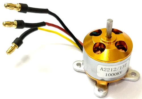
So basically in this tutorial we will Control Brushless Motor with Arduino. Here A2212/13T Sensorless BLDC outrunner motor is used with a 20A Electronic Speed Controller (ESC). This motor is commonly used to build drones.
Materials Required
- A2212/13T BLDC Motor
- ESC (20A)
- Power Source (12V 20A)
- Arduino
- Potentiometer
Understanding BLDC Motors
BLDC Motor stands for Brush Less DC motor, it is commonly used in ceiling fans and electric vehicles due to its smooth operation. Use of BLDC motors in electric vehicles is previously explained in detail. Unlike other motors, the BLDC motors have three wires coming out of them and each wire forms its own phase thus given us a three phase Motor. Wait... what!!??
Yes, although BLDC motors are considered to be DC motors, they work with the help of Pulsed waves. The Electronic speed controller (ESC) converts the DC voltage from the battery in to pulses and provides it to the 3 wires of the Motor. At any given time only two Phase of the motor will be powered, so that current enters through one phase and leaves through other. During this process the coil inside the motor is energised and hence the magnets on the rotor align itself to the energised coil. Then the next two wires are energised by the ESC, this process is continued to make the motor rotate. The speed of the motor depends on how fast the coil is energised and direction of motor depends on in which order the coils are energised. We will learn more about ESC later in this article.
There are many types of BLDC motors available, let’s take look at the most common classifications.
In-runner and Out-Runner BLDC motor: In runner BLDC Motors work like any other motor. That is the shaft inside the motor rotates while casing remains fixed. While out runner BLDC motors are just the opposite, the Outer casing of the motor rotates along with the shaft while the coil inside stays fixed. Out runner motors are very advantages in Electric bikes since the outer casing (the one that rotates) itself is made into a Rim for the tyres and hence a coupling mechanism is avoided. Also the out runner motors tend to give more torque than in runner types, hence it becomes an ideal choice in EV and Drones. The one that we are using here is also an out runner type.
Note: There is another type of motor called the coreless BLDC motors which are also used for pocket Drones, they have a different working principle but for now let’s skip it for the sake of this tutorial.
Sensor and Sensorless BLDC Motor: For a BLDC motor to rotate without any jerk a feedback is required. That is the ESC has to know the position and pole of the magnets in the rotor so as to energise the stator according. This information can be acquired in two ways; one is by placing hall sensor inside the motor. The hall sensor will detect the magnet and send the information to ESC this type of motor is called a Sensord BLDC motor and is used in Electric vehicles. The second method is by using the back EMF generated by the coils when the magnets cross them, this required not additional hardware or wires the phase wire itself is used as a feedback to check for back EMF. This method is used in our motor and is common for drones and other flying projects.
Why do Drones and other Multi-copters use BLDC Motors?
There are many types of cool drones out there from Quad copter to helicopters and gliders everything has one hardware in common. That is the BLDC motors, but why? Why do they use a BLDC motor which is a bit expensive compared to DC Motors?
There are quite a few valid reasons for this, one main reason is the torque provided by these motors are very high which is very important to gain/loose thrust rapidly to take off or land down a drone. Also these motors are available as out runners which again increases the thrust of the motors. Another reason for select BLDC motor is its smooth vibration less operation, this is very ideal to our drone stable in mid-air.
The power to weight ratio of a BLDC motor is very high. This is very important because the motors used on drones should be of high power (high speed and high torque) but should also be of less weight. A DC motor which could provide the same torque and speed of that of a BLDC motor will be twice as heavy as the BLDC motor.
Why do we need an ESC and what is its function?
As we know every BLDC motor requires some sort of controller to convert the DC voltage from the battery into pulses to power the phase wires of the motor. This controller is called an ESC which stands for Electronic Speed Controller. The main responsibility of the controller is to energise the Phase wires of the BLDC motors in an order so that the motor rotates. This is done by sensing the back EMF from each wire and energise the coil exactly when the magnet crosses the coil. So there is a lot of hardware brilliance inside the ESC which is out of the scope of this tutorial. But to mention a few it has speed controller and a battery eliminator circuit.
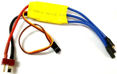
PWM based speed control: The ESC can control the speed of the BLDC motor by reading the PWM signal provided on the Orange wire. It works very much similar to servo motors, the provided PWM signal should have a period of 20ms and the duty cycle can be varied to vary the speed of the BLDC motor. Since the same logic also applies for the servo motors to control the position we can use the same servo library in our Arduino program. Learn using Servo with Arduino here.
Battery Eliminator Circuit (BEC): Almost all ESC’s comes with a Battery eliminator circuit. As the name suggests this circuit eliminates the need of separate battery for microcontroller, in this case we do not need a separate power supply to power our Arduino; the ESC itself will provide a regulated +5V which can be used power our Arduino. There are many types of circuit which regulates this voltage normally it will be linear regulation on the cheap ESCs, but you can also find ones with switching circuits.
Firmware: Every ESC has a firmware program written into it by the manufactures. This firmware greatly determines how your ESC responds; some of the popular firmware is Traditional, Simon-K and BL-Heli. This firmware is also user programmable but we will not get into much of that in this tutorial.
Some common terms with BLDC and ESC’s:
If you have just started to work with BLDC motors then you might have probably come across the terms like Braking, Soft start, Motor Direction, Low Voltage, Response time and Advance. Let’s take a look into what these terms mean.
Braking: Braking is the ability of your BLDC motor to stop rotating as soon as the throttle is removed. This ability is very important for multi-copters since they have to change their RPM more often to manoeuvre in the air.
Soft Start: Soft start is an important feature to consider when your BLDC motor is associated with gear. When a motor has soft start enabled, it will not start rotating very fast all of a sudden, it will always gradually increase the speed no matter how quickly the throttle was given. This will help us in reducing the wear and tear of gears attached with the motors (if any).
Motor Direction: The motor direction in BLDC motors are normally not changed during operation. But when assembling, the user might need to change the direction in which the motor is rotating. The easiest way to change the direction of the motor is by simply inter changing any two wires of the motor.
Low Voltage Stop: Once calibrated we would always need our BLDC motors run at the same particular speed for a particular value of throttle. But this is hard to achieve because the motors tend to reduce their speed for the same value of throttle as the battery voltage decreases. To avoid this we normally program the ESC to stop working when the battery voltage has reached below the threshold value this function is called Low Voltage Stop and is useful in drones.
Response time: The ability of the motor to quickly change its speed based on the change in throttle is called response time. The lesser the response time is the better the control will be.
Advance: Advance is a problem or more like a bug with BLDC motors. All BLDC motors have a little bit of advance in them. That is when the stator coils are energised the rotor is attracted towards it because of the permanent magnet present on them. After getting attracted the rotor tends to move a bit more forward in that same direction before the coil de-energises and then next coil energises. This movement is called “Advance” and it will create problems like jittering, heating up, making noise etc. So this is something a good ESC should avoid on its own.
Okay, enough theory now let us get started with the hardware by connecting the motor with the Arduino.

Arduino BLDC Motor Control Circuit Diagram
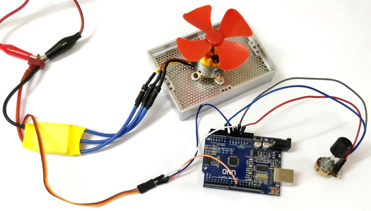
Below is the circuit diagram to Control Brushless Motor with Arduino:

The connection for interfacing BLDC motor with Arduino is pretty straight forward. The ESC needs a powers source of around 12V and 5A minimum. In this tutorial I have used my RPS as a power source but you can also use a Li-Po battery to power the ESC. The three phase wires of the ESC should be connected to the three phase wires of the motors, there is no order to connect these wires you can connect them in any order.
Warning: Some ESC will not have connectors on them, in that case make sure your connection is solid and protect the exposed wires using insulation tape. Since there will be high current passing through the phases any short would lead to permanent damage of the ESC and motor.
The BEC (Battery Eliminator circuit) in the ESC itself will regulate a +5V which can be used to power up the Arduino Board. Finally to set the speed of the BLDC motor we also use a potentiometer connected to A0 pin of the Arduino
Program for BLDC Speed Control using Arduino
We have to create a PWM signal with varying duty cycle from 0% to 100% with a frequency of 50Hz. The duty cycle should be controlled by using a potentiometer so that we can control the speed of the motor. The code to do this is similar to controlling the servo motors since they also require a PWM signal with 50Hz frequency; hence we use the same servo library from Arduino. The complete code can be found at the bottom of this page further below I explain the code in small snippets. And if you are new to Arduino or PWM then, first go through using PWM with Arduino and controlling servo using Arduino.
The PWM signal can be generated only on the pins which support PWM by hardware, these pins are normally mentioned with a ~ symbol. On Arduino UNO, the pin 9 can generate PWM signal so we connect the ESC signal pin (orange wire) to pin 9 we also mention the same inn code by using the following line
ESC.attach(9);
We have to generate PWM signal of varying duty cycle from 0% to 100%. For 0% duty cycle the POT will output 0V (0) and for 100% duty cycle the POT will output 5V (1023). Here the pot is connected to pin A0, so we have to read the analog voltage from the POT by using the analog read function as shown below
int throttle = analogRead(A0);
Then we have to convert the value from 0 to 1023 to 0 to 180 because the value 0 will generate 0% PWM and value 180 will generate 100% duty cycle. Any values above 180 will make no sense. So we map the value to 0-180 by using the map function as shown below.
throttle = map(throttle, 0, 1023, 0, 180);
Finally, we have to send this value to the servo function so that it can generate the PWM signal on that pin. Since we have named out servo object as ESC the code will look like this below, where the variable throttle contains the value from 0-180 to control the duty cycle of the PWM signal
ESC.write(throttle);
Arduino BLDC Motor Control
Make the connections according to the circuit diagram and upload the code to Arduino and power up the ESC. Make sure you have mounted the BLDC motor onto something since the motor will jump all around when rotating. Once the setup is powered on, your ESC will make a welcome tone and will keep beeping until the throttle signal is within the threshold limits, simple increase the POT from 0V gradually and the beeping tone will stop, this means that we are now providing PWM signal above the lower threshold value and as you increase further your motor will start rotating slowly. The more voltage you provide the more speed the motor will pick up, finally when the voltage reaches above the upper threshold limit the motor will stop. You can then repeat the process.
The complete working of this Arduino BLDC Controller can also be found at the video link below. If you had faced any problem on getting this to work feel free to use the comment section or use the forums for more technical help.
Complete Project Code
#include <Servo.h> //Use the Servo librarey for generating PWM

Servo ESC; //name the servo object, here ESC
void setup()

{

ESC.attach(9); //Generate PWM in pin 9 of Arduino

}
void loop()

{

int throttle = analogRead(A0); //Read the voltage from POT

throttle = map(throttle, 0, 1023, 0, 180); //Map the values of 0-102 from pot to 0-180 bcs servo works only from 0-180

ESC.write(throttle); //based on the value of throttle generate PWM signal

}
Comments
diagram error
In the third diagram that shows the connection of esc ,BLDC and arduino .
the wire that goes from the esc to the (5v) pin of the arduino
must go to (vin) pin not (5v) pin
good luck;
Ibrahim Fathi ;
Egypt;
No it should be connected to 5V pin only
You have got it wrong Ibrahim, the ESC provides a regulated 5V which should be used to power the Arduino thorugh its 5V pin. The Vin pin is used for providing unregulated voltage
Sir can use 30 amp esc
Sir can use 30 amp esc instead of 20 amp esc for remaining are same rating
Hello, First of all, thank…
Hello,
First of all, thank you for this great article. I had no idea it is so easy to use ESC with Arduino.
I have few questions for you please…
Once you change the throttle, does the engine keep rotating or do I have to keep declaring it in loop again and again? What I mean is you can set it to 50% once and does the engine keep rotating on this rate?
and
If I want to power Arduino with another separate power suplly and not the 5V from ESC, where do I plug the 5V cable from ESC?
Thank you once again, Marek.

Brushless motors $?