
Most heart diseases are associated with and reflected by the sound that the heart produces, and one of the easiest and cheapest ways of diagnosing cardiac dysfunction is by Heart auscultation i.e listening to the heart sound. Now if we are talking about traditional auscultation, that requires experience and good listening skills. That is why in this project we thought to build an electronic stethoscope that will be able to get the heart rate of the human body and we can display the data in a Bluetooth-based serial terminal window. So without further ado let's get started.
How Does Wireless Digital Stethoscope Work?
Before we go any further in the article, let's discuss how this circuit works.
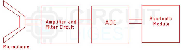
In order to get the heartbeat data, we will first get a stethoscope and cut it in half to fit a condenser microphone, so that we could get the heartbeat sound from the stethoscope. Next, we will make an amplifier with an op-amp and amplify the signal from the microphone so that we could read it with the ADC of the Arduino. But before reading the signal, we will pass it through a low pass filter that will reject all the unnecessary noise and signal and we will get a pure heartbeat signal on the output. Next, we will send this data to a Bluetooth terminal window with the help of the HC-05 Bluetooth module.
Components Required to build the Wireless Stethoscope
The components required to build the wireless stethoscope are very generic and most of them you can find in your local hobby store. The list of components is given below.
- Arduino UNO
- HC-05 Bluetooth Module
- NE5532 Op-Amp - 1
- Dual Polarity Power Supply
- Perfboard - 1
- 1K Resistor - 2
- 3.3K Resistor 1
- 10K Resistor - 3
- 100K Resistor - 1
- 470nF Capacitor - 1
- 2.2uF capacitor - 1
Schematic Diagram of the Wireless Stethoscope

The schematic diagram of the wireless stethoscope is very simple and easy to understand. First, the heartbeat is picked up by a condenser microphone and we have a 1uF DC blocking capacitor to block all the DC components of the output signal. Next, we have a non-inverting amplifier with its gain set to 100X. We set the gain to 100X with the help of the 1k and 100K resistor to amplify the received signal by a microphone. Once the signal is amplified, we pass it through a low pass filter, the low pass filter rejects all the signal components above 300 HZ and passes only that range of the signal. After that we have a voltage divider circuit as we are using a 12-0-12 V transformer to power the practical circuit, the output of the op-amp will vary so you need to adjust the voltage divider according to that so the values for the R1 and R2 are not given in the schematic. Once that is done, we convert the signal with the help of an ADC and we calculate the heartbeat from the ADC signal, and send the data with the help of the connected Bluetooth module.
Code for Bluetooth-Based Wireless Stethoscope
The code for Bluetooth-based wireless stethoscope is very simple and easy to understand. We start our code by including all the required libraries. For this project, we only need one library to communicate with the Bluetooth module which is the software serial library,
#include <SoftwareSerial.h>
Next, we need to include the required variables. We have defined variables to store the ADC value and a counter that holds the number of pulses in a certain period of time. We also have an interval variable that holds a millisecond value, we will use this variable to take a sample of the heartbeat and then calculate the average of the variables. We also have a variable named previousMillis that holds the counter data and is used to compare with the millis counter.
const int analogInPin = A0;  // Analog input pin that the potentiometer is attached to
int sensorValue = 0;
unsigned long counter = 0;
int interval = 5000;
unsigned long previousMillis = 0;
Next, we have initialized the softserial and made an instance called BTserial. Through this, we can communicate with the Bluetooth serial module.
SoftwareSerial BTserial(3, 4); // RX | TX
Next, we have our setup function. In the setup function, we call the begin method of the serial and BTserial instance with 9600 baud. So that we can debug through the Arduino and simultaneously communicate with the Bluetooth module.
void setup() {
  Serial.begin(9600);
  BTserial.begin(9600);
}
Next, we have the loop function. In the loop function, we declare two variables currentMillis, and currentMillis2. These will hold two current time stamps and will be useful later in the code.
unsigned long currentMillis = millis();
unsigned long currentMillis2 = millis();
Next, we have an if statement. In the if statement, we check if 30 seconds is passed or not if so we go to the next while loop. Inside the while loop, we take the ADC data and check if the received value is within a certain range if so, we increment the counter, incrementing the counter means that we have recognized a heartbeat. Now we reset all the variables and print the heartbeat account onto the serial monitor window, and we also send the data through Bluetooth.
 if ((unsigned long)(currentMillis2 - previousMillis2) >= interval2)
  {
    while ((currentMillis - previousMillis ) < interval)
    {
      sensorValue = analogRead(analogInPin);
      if (sensorValue > 130 && sensorValue < 250)
      {
        counter++;
      }
    }
    previousMillis = currentMillis;
    previousMillis2 = currentMillis2;
    Serial.println(counter);
    BTserial.write(counter);
  }
}
This marks the end of our code section and we can move on to the next section, which is the testing section of the article.
Testing the Wireless Stethoscope Circuit
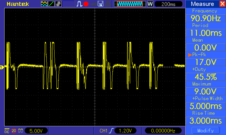
Once the circuit build was finished we put the stethoscope in and we check for waveforms. For that, we first hit the diaphragm of the stethoscope with a finger and that produces the result that is shown below-
Next, I put the stethoscope on my chest and observed the waveform, and it looks like the image shown below-
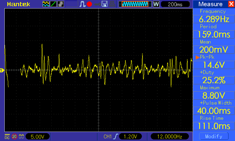
As you can see from the above image, the peek-to-peek voltage coming out of the op-amp is around 14.6V.
Next, we open the serial monitor window and check if the serial data was accurate or not, and the data was getting printed accurately on the serial monitor window.
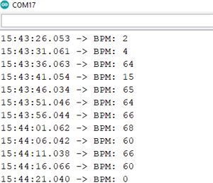
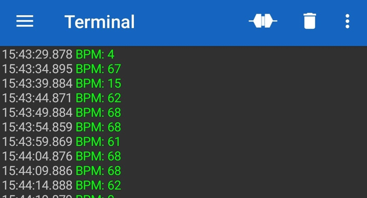
Next, we paired the Bluetooth with our phone and downloaded the Bluetooth serial terminal android application, and connected the Bluetooth with the serial terminal. Once everything was done you can see we were able to get data in the serial terminal window.

Issues We Faced During the Building Process
There are many issues that we faced during the building process, and among them, the most significant one was mounting the microphone to the pipe of the stethoscope. For that, we had to scrape the pipe of the stethoscope a lot and then apply heat in order to make the pipe bigger and then we used super glue to secure the microphone with the pipe of the stethoscope.
The next big issue was with the noise. There is random noise that is generated when the pipe of the stethoscope is rubbed with clothes, so we need to add a low pass filter at the output of the op-amp stage.
Next, we had to filter the ADC data with software, for that average the data with for loop in order to get the output of the module stable.
Complete Project Code
#include <SoftwareSerial.h>
const int analogInPin = A0;  // Analog input pin that the potentiometer is attached to
int sensorValue = 0;
unsigned long counter = 0;
int interval = 5000;
int interval2 = 5000;
unsigned long previousMillis = 0;
unsigned long previousMillis2 = 0;
SoftwareSerial BTserial(3, 4); // RX | TX
void setup() {
  Serial.begin(9600);
  BTserial.begin(9600);
}
void loop() {
  unsigned long currentMillis = millis();
  unsigned long currentMillis2 = millis();
  if ((unsigned long)(currentMillis2 - previousMillis2) >= interval2)
  {
    while ((currentMillis - previousMillis ) < interval)
    {
      sensorValue = analogRead(analogInPin);
      if (sensorValue > 130 && sensorValue < 250)
      {
        counter++;
      }
    }
    previousMillis = currentMillis;
    previousMillis2 = currentMillis2;
    Serial.println(counter);
    BTserial.write(counter);
  }
}
Comments
Hello, I am a beginner and…
Hello, I am a beginner and looking for some help regarding your project. I have implemented a similar setup upto some extent. At this point, I am not able to complete this project. Can you respond asap.
Hello, I am a beginner and…
Hello, I am a beginner and looking for some help regarding your project. I have implemented a similar setup upto some extent. At this point, I am not able to complete this project. Can you respond asap.
Hello, I am a beginner and…
Hello, I am a beginner and looking for some help regarding your project. I have implemented a similar setup upto some extent. At this point, I am not able to complete this project. Can you respond asap.
Si, I have make the same…
Si, I have make the same circuit but it is not giving me bpm value or graph.How to solve this problem?

i am trying to do the experiment above but i am stuck with what software to use to monitor data and other than that is there any way to contact you i have few doubts on how to do it