

Obstacle Avoider Robot is another famous robot which spices up embedded projects. For those who are new Obstacle avoider robot, it is just a normal wheeled robot which could navigate its way without hitting on any obstacles. There are many way to build a Obstacle avoider robot in project we are going to use one Ultrasonic Sensor (front) and two IR sensor (Left/Right) so that our robot has eyes in all three directions. This way you can make it much smarter and faster by detecting objects in all three sides and manoeuvre accordingly. Here we are suing PIC Microcontroller PIC16F877A for this obstacle avoiding robot.
The operation of an obstacle avoiding robot can be observed from a real time product called Home cleaning robots. Though the technology and sensors used in these are much complicated, the concept remains the same. Let us see how much we can accomplish using our normal sensors and PIC microcontrollers.
Also check our other Obstacle Avoiding Robots:
Materials Required:
- PIC16F877A
- IR Sensor (2Nos)
- Ultrasonic Sensor (1Nos)
- DC Gear Motor (2Nos)
- L293D Motor Driver
- Chaises (You can also build your own using cardboards)
- Power bank (Any available power source)
Concept of Obstacle Avoiding Robot:
The concept of Obstacle Avoiding Robot is very simple. We use sensors to detect the presence of objects around the robot and use this data to not collide the robot over those objects. To detect an Object we can use any use sensors like IR sensor and Ultrasonic sensor.


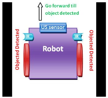
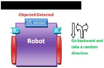
In our robot we have used the US sensor as the front sensor and two IR sensor for the left and right respectively. The robot will move forward when there is no object present before it. So robot will move forward until the Ultrasonic (US) sensor detects any object.
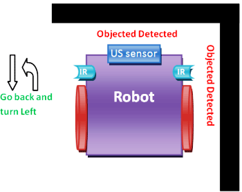
When an object is detected by the US sensor, it is time to change the direction of the robot. We can either turn left or right, to decide the turning direction we use the help of IR sensor to check if there is any object present near the Left or right side of the robot.
If there is an objected detected on the front and right side of the Robot, then the robot will come back and turn left. We make the robot to run backward for a certain distance so that it does not collide on the object while making the turn.
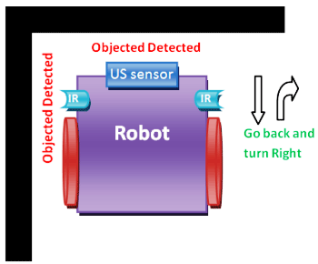
If there is an objected detected on the front and left side of the Robot, then the robot will come back and turn right.
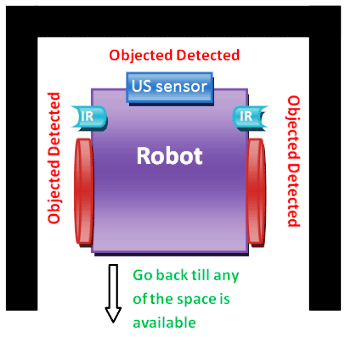
If the robot reaches a corner of the room it will sense object present in all four. In this case we have to drive the robot backward until any of the side becomes free.
Another possible case is that there will be an object in front but there might not be any object neither in the left side nor on the right side, in this case we have to randomly turn in any of the direction.
Hope this would have given a rough idea of how an Obstacle avoider works, now let’s proceeds with the Circuit Diagram to build this bot and enjoy it in action.
Circuit Diagram and Explanation:

The complete circuit Diagram of the this PIC based obstacle avoiding robot is shown in the above picture. As you can see we have used two IR sensors to detect objects on left and right of the robot respectively and a Ultrasonic sensor to measure the distance of the object that is present ahead of the robot. We have also used a L293D Motor Driver module to Drive the two motor present in this project. These are just ordinary DC gear motors for wheels and hence can be derived very easily. The following table will assist you in connections.
|
S.No |
Connected from |
Connected to |
|
1 |
IR sensor Left out pin |
RD2 (pin 21) |
|
2 |
IR sensor Right out pin |
RD3 (pin 22) |
|
4 |
Motor 1 Channel A pin |
RC4 (pin 23) |
|
5 |
Motor 1 Channel B pin |
RC5 (pin 25) |
|
6 |
Motor 2 Channel A pin |
RC6 (pin 26) |
|
7 |
Motor 2 Channel B pin |
RC7 (pin 27) |
|
8 |
US Trigger Pin |
RB1 (pin 34) |
|
9 |
US Echo Pin |
RB2 (pin 35) |
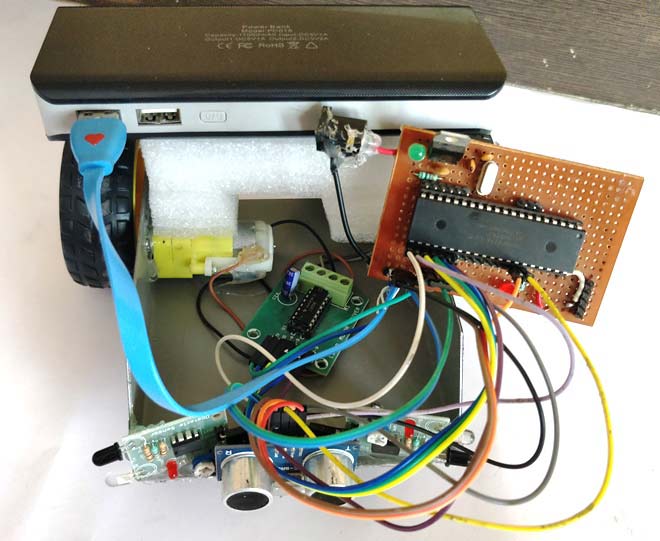
A motor Driver module like L293D is mandatory because the amount of current required for running the DC gear motor cannot be sourced by the I/O pin of the PIC microcontroller. The sensors and the module is powered by the +5V supply which is being regulated by the 7805. The motor driver module can be powered even using +12V, but for this project I have just stuck on to the available +5V.
The complete Robot is powered by a Power bank in my case. You can also use any ordinary power bank and by pass the regulator section or use the above circuit and use any 9V or 12V battery for the Robot as shown in the circuit diagram above. Once your connections are done it would look something like this below
Programming you PIC Microcontroller:
Programming you PIC to work for a Obstacle avoider is really easy. We just have to read the value of these three sensors and drive the Motors accordingly. In this project we are using a Ultrasonic sensor. We have already learnt how to interface ultrasonic with PIC microcontroller, if you are new here kindly fall back to that tutorial to understand how a US sensor works with a PIC, since I will be skipping the details about it here to avoid repetition.
The complete program or this Robot is given at the end of this page, I have further explained the important chunks of the program below.
As we know all programs starts with the Input and Output pin declarations. Here the Four pins of the Motor Driver module and the Trigger pins are the Output pins, while the Echo pin and two IR out pins will be input. We should initialize the Timer 1 module to use it with the Ultrasonic sensor.
  TRISD = 0x00; //PORTD declared as output for interfacing LCD
     TRISB1 = 0; //Trigger pin of US sensor is sent as output pin
     TRISB2 = 1; //Echo pin of US sensor is set as input pin
     TRISB3 = 0; //RB3 is output pin for LED

     TRISD2 = 1; TRISD3 = 1; //Both the IR sensor pins are declared as input
     TRISC4 = 0; TRISC5 = 0; //Motor 1 pins declared as output
     TRISC6 = 0; TRISC7 = 0; //Motor 2 pins declared as output

     T1CON=0x20;
In this program we would have to check for the distance between the sensor and the object quite often, so we have created a function named calculate_distance() inside which we will measure the distance by the method discussed in the US sensor interfacing tutorial. The code is shown below
     void calculate_distance() //function to calculate distance of US
     {
         TMR1H =0; TMR1L =0; //clear the timer bits

        Trigger = 1;
        __delay_us(10);
        Trigger = 0;

        while (Echo==0);
            TMR1ON = 1;
        while (Echo==1);
            TMR1ON = 0;

        time_taken = (TMR1L | (TMR1H<<8));
        distance= (0.0272*time_taken)/2;
     }
The next step would be to compare the values of Ultrasonic sensor and IR sensor and move the robot accordingly. Here In this program I have used a value of cm as the critical distance below which the Robot should start making changes to the direction. You can use your preferred values. If there is not object the robot just moves forward
if (distance>5)
        {
         RC4=0; RC5=1; //Motor 1 forward
         RC6=1; RC7=0; //Motor 2 forward
        }
If an object is detected, then the distance will go below cm. In this case we consider the values of left and right Ultrasonic sensor. Based in this value we decide either to turn left or turn right. A delay of ms is used so that the change is direction is visible.
if (RD2==0 && RD3==1 && distance<=5) //Left sensor is blocked
         {
         back_off();
         RC4=1; RC5=1; //Motor 1 stop
         RC6=1; RC7=0; //Motor 2 forward
         __delay_ms(500);
         }


        calculate_distance();
         if (RD2==1 && RD3==0 && distance<=5) //Right sensor is blocked
         {
         back_off();
         RC4=0; RC5=1; //Motor 1 forward
         RC6=1; RC7=1; //Motor 2 stop
         __delay_ms(500);
         }
Sometimes the Ultrasonic sensor would detect an object, but there would no object detected by the IR sensors. In this case the robot turns left by default. You can also make it turn right or at a random direction based on your preferences. If there are objects on both the sides then we make it go backward. The code for doing the same is shown below.
     calculate_distance();
         if (RD2==0 && RD3==0 && distance<=5)//Both sensor is open
         {
         back_off();
         RC4=0; RC5=1; //Motor 1 forward
         RC6=1; RC7=1; //Motor 2 stop
         __delay_ms(500);
         }

        calculate_distance();
         if (RD2==1 && RD3==1 && distance<=5)//Both sensor is blocked
         {
         back_off();
         RC4=1; RC5=0; //Motor 1 reverse
         RC6=1; RC7=1; //Motor 2 stop
         __delay_ms(1000);
         }
Obstacle Avoider Robot in Action:
The working of the project is very interesting and fun to watch. Once you are done with your Circuit and Code, just power on your Bot and leave it on the ground. It should be able to identify obstacles and avoid them smartly. But, here comes the fun part. You can modify the code and make it do more stuff like making it avoid a stair, making it smarter by storing precious turns and what not?
This Robot will help you understand the basic of programming and learn how an actual hardware will respond to your code. It is always fun to program this robot and watch how it behaves for the code in real world.
Here we have used the same PIC perf board which we have made for blinking LED using PIC microcontroller and used this board in other projects of PIC Tutorial Series.
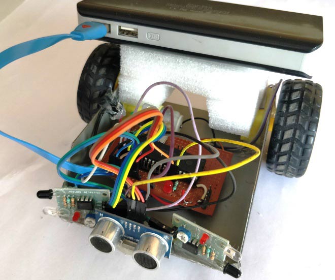
Your robot should look something similar to the one shown in the picture above. The complete working of this project is shown in the video below.
Hope you understood the project and enjoyed building one. If you have any doubts or got stuck you can use the comment section to post your questions and I will try my best in answering them.
Complete Project Code
/*

Obstacle avoider using PIC16F877A

 * Code by: B.Aswinth Raj

 * Dated: 03-10-2017

 * More details at: www.CircuitDigest.com

 */
#include <xc.h>
#pragma config FOSC = HS        // Oscillator Selection bits (HS oscillator)

#pragma config WDTE = OFF       // Watchdog Timer Enable bit (WDT disabled)

#pragma config PWRTE = ON       // Power-up Timer Enable bit (PWRT enabled)

#pragma config BOREN = ON       // Brown-out Reset Enable bit (BOR enabled)

#pragma config LVP = OFF        // Low-Voltage (Single-Supply) In-Circuit Serial Programming Enable bit (RB3 is digital I/O, HV on MCLR must be used for programming)

#pragma config CPD = OFF        // Data EEPROM Memory Code Protection bit (Data EEPROM code protection off)

#pragma config WRT = OFF        // Flash Program Memory Write Enable bits (Write protection off; all program memory may be written to by EECON control)

#pragma config CP = OFF         // Flash Program Memory Code Protection bit (Code protection off)
#define _XTAL_FREQ 20000000

#define Trigger RB1 //34 is Trigger

#define Echo RB2//35 is Echo
int time_taken;

int distance;


     void back_off() //used to drive the robot backward

     {

      RC4=1; RC5=0; //Motor 1 reverse

      RC6=0; RC7=1; //Motor 2 reverse

      __delay_ms(1000);

     }


     void calculate_distance() //function to calculate distance of US

     {

         TMR1H =0; TMR1L =0; //clear the timer bits


        Trigger = 1;

        __delay_us(10);

        Trigger = 0;


        while (Echo==0);

            TMR1ON = 1;

        while (Echo==1);

            TMR1ON = 0;


        time_taken = (TMR1L | (TMR1H<<8));

        distance= (0.0272*time_taken)/2;

     }


void main()

{

     TRISD = 0x00; //PORTD declared as output for interfacing LCD

     TRISB1 = 0; //Trigger pin of US sensor is sent as output pin

     TRISB2 = 1; //Echo pin of US sensor is set as input pin

     TRISB3 = 0; //RB3 is output pin for LED


     TRISD2 = 1; TRISD3 = 1; //Both the IR sensor pins are declared as input

     TRISC4 = 0; TRISC5 = 0; //Motor 1 pins declared as output

     TRISC6 = 0; TRISC7 = 0; //Motor 2 pins declared as output


     T1CON=0x20;


     while(1)

         {


        calculate_distance();

        if (distance>5)

        {

         RC4=0; RC5=1; //Motor 1 forward

         RC6=1; RC7=0; //Motor 2 forward

        }


        calculate_distance();

         if (RD2==0 && RD3==1 && distance<=5) //Left sensor is blocked

         {

         back_off();

         RC4=1; RC5=1; //Motor 1 stop

         RC6=1; RC7=0; //Motor 2 forward

         __delay_ms(500);

         }


        calculate_distance();

         if (RD2==1 && RD3==0 && distance<=5) //Right sensor is blocked

         {

         back_off();

         RC4=0; RC5=1; //Motor 1 forward

         RC6=1; RC7=1; //Motor 2 stop

         __delay_ms(500);

         }


        calculate_distance();

         if (RD2==0 && RD3==0 && distance<=5)//Both sensor is open

         {

         back_off();

         RC4=0; RC5=1; //Motor 1 forward

         RC6=1; RC7=1; //Motor 2 stop

         __delay_ms(500);

         }


        calculate_distance();

         if (RD2==1 && RD3==1 && distance<=5)//Both sensor is blocked

         {

         back_off();

         RC4=1; RC5=0; //Motor 1 reverse

         RC6=1; RC7=1; //Motor 2 stop

         __delay_ms(1000);

         }


         }

}
Comments
Post the Error message here,
Post the Error message here, so as to help you
which compiler that you are using?
Hello. May i know what compiler that you are using? is it mikroC Pro?
Would I be able to implement
Would I be able to implement this using a PIC curiosity board HPC? I would like to know. I would appreciate your help. Thank you
Yes you can. The logic will
Yes you can. The logic will remain the same
Obstacle Avoiding Robot using PIC Microcontroller
i have probleme with code of c
Normal servos, can rotate
Normal servos, can rotate only from 0-180*. If you have a servo that is 360* then yes you can use it
Hello am using the pic18f2220
Hello am using the pic18f2220 what changes would I need to make?
could you expain these
could you expain these equations?
time_taken = (TMR1L | (TMR1H<<8));
distance= (0.0272*time_taken)/2;
The amount of time taken for
The amount of time taken for the wave to hit an object and return will be stored int he TMR1 register. This register is a 16-bit register so the values in this register are stored in two 8 bit registers TMR1L and TMR1H.
(TMR1L | (TMR1H<<8)) by doing this we are combining the two 8-bit data to get a 16-bit data and storing the result in the variable time_taken.
Next to find distance we use the formulae speed= (distance/time). Since the wave is hitting the object and returning we divide the value by two. The value 0.0272 is the value of speed of us wave.
Hope this clears your doubt
The program will compile only
The program will compile only on XC8 compiler, so try it only using XC8
How if i want to use
How if i want to use pic18f4550? What i need to change in source code?
Nothing much except for the
Nothing much except for the configuration registers just refer the datasheet it should be easy
RUNNING THE SAME CODE ON PIC18
HI! did you get any clue of the necessary changes that are to be made in the code to use it for pic18??
I tried building the same
I tried building the same robo under your instructions but I am having a issue.Sometime the robo works but sometimes it doesnot.Sometime only a single motor works .I am really confused about that.I checked connections many times they all are fine.Secondly is backoff() a bult in function ?
Can i have the L293D
Can i have the L293D connection to the PIC and the motor? From ur diagram, which pin is enable 1,2 and which pin is the input and output? urgent....thank you
Folllow the circuit diagram
Folllow the circuit diagram given by the author. The enable pins are optional to use and is not used in this project
how to change the program if
how to change the program if i using 3 ultrasonic sensors instead of one ultrasonic & 2 IR sensors?
Can anyone please help me to troubleshoot this code?
#pragma config FOSC = HS // Oscillator Selection bits (HS oscillator)
#pragma config WDTE = OFF // Watchdog Timer Enable bit (WDT disabled)
#pragma config PWRTE = ON // Power-up Timer Enable bit (PWRT enabled)
#pragma config BOREN = ON // Brown-out Reset Enable bit (BOR enabled)
#pragma config LVP = OFF // Low-Voltage (Single-Supply) In-Circuit Serial Programming Enable bit (RB3 is digital I/O, HV on MCLR must be used for programming)
#pragma config CPD = OFF // Data EEPROM Memory Code Protection bit (Data EEPROM code protection off)
#pragma config WRT = OFF // Flash Program Memory Write Enable bits (Write protection off; all program memory may be written to by EECON control)
#pragma config CP = OFF // Flash Program Memory Code Protection bit (Code protection off)
#include <xc.h>
#define _XTAL_FREQ 20000000
#define Trigger RB1 //34 is Trigger
#define Front_Echo RB2//35 is Echo
#define Left_Echo RB3//36 is Echo
#define Right_Echo RB4//37 is Echo
void back_off();
void calculate_front_distance();
void calculate_left_distance();
void calculate_right_distance();
int ftime_taken;
int ltime_taken;
int rtime_taken;
int front_distance;
int left_distance;
int right_distance;
void calculate_front_distance() //function to calculate front distance of US
{
TMR1H =0; TMR1L =0; //clear the timer bits
Trigger = 1;
__delay_us(10);
Trigger = 0;
while (Front_Echo==0);
TMR1ON = 1;
while (Front_Echo==1);
TMR1ON = 0;
ftime_taken = (TMR1L | (TMR1H<<8));
front_distance= (0.0272*ftime_taken)/2;
}
void calculate_left_distance() //function to calculate left distance of US
{
TMR1H =0; TMR1L =0; //clear the timer bits
Trigger = 1;
__delay_us(10);
Trigger = 0;
while (Left_Echo==0);
TMR1ON = 1;
while (Left_Echo==1);
TMR1ON = 0;
ltime_taken = (TMR1L | (TMR1H<<8));
left_distance= (0.0272*ltime_taken)/2;
}
void calculate_right_distance() //function to calculate right distance of US
{
TMR1H =0; TMR1L =0; //clear the timer bits
Trigger = 1;
__delay_us(10);
Trigger = 0;
while (Right_Echo==0);
TMR1ON = 1;
while (Right_Echo==1);
TMR1ON = 0;
rtime_taken = (TMR1L | (TMR1H<<8));
right_distance= (0.0272*rtime_taken)/2;
}
void back_off() //used to drive the robot backward
{
RC4=1; RC5=0; //Motor 1 reverse
RC6=0; RC7=1; //Motor 2 reverse
__delay_ms(1000);
}
void main()
{
TRISD = 0x00; //PORTD declared as output
TRISB1 = 0; //Trigger pin of US sensor is sent as output pin
TRISB2 = 1; //Echo pin of US sensor is set as input pin (Front)
TRISB3 = 1; //Echo pin of US sensor is set as input pin (Left)
TRISB4 = 1; //Echo pin of US sensor is set as input pin (Right)
TRISD4 = 0; TRISD5 = 0; //Motor 1 pins declared as output
TRISD6 = 0; TRISD7 = 0; //Motor 2 pins declared as output
T1CON=0x20;
while(1)
{
if (front_distance>5)
{
RD4=0; RD5=1; //Motor 1 forward
RD6=1; RD7=0; //Motor 2 forward
}
else if (left_distance<=5 && right_distance>5 && front_distance<=5)//Left US is blocked
{
back_off();
RD4=1; RD5=1; //Motor 1 stop
RD6=1; RD7=0; //Motor 2 forward
}
else if (left_distance>5 && right_distance<=5 && front_distance<=5) //Right sensor is blocked
{
back_off();
RC4=0; RC5=1; //Motor 1 forward
RC6=1; RC7=1; //Motor 2 stop
__delay_ms(500);
}
else if (left_distance>5 && right_distance>5 && front_distance<=5)//Both sensor is open
{
back_off();
RC4=0; RC5=1; //Motor 1 forward
RC6=1; RC7=1; //Motor 2 stop
__delay_ms(500);
}
else if (left_distance<=5 && right_distance<=5 && front_distance<=5)//Both sensor is blocked
{
back_off();
RC4=1; RC5=0; //Motor 1 reverse
RC6=1; RC7=1; //Motor 2 stop
__delay_ms(1000);
}
}
}
Circuit Diagram
Kind of an off topic question but can anyone tell me what program was used for the circuit diagram?
if i use the same code in
if i use the same code in pic18f4520 what necessary changes will i have to make to run the code?
kindly tell in detail
Garmin LIDAR-Lite v3 as replacement for Ultronic sensor
I would like to build this project but would like to use a LIDAR in the place of the u;tronic sensor, but have no idea where to start.
Would be grateful for some ideas such as hardware connections and codes.
Thanks
Jamesd
Can we use universal
Can we use universal programmer other than PicKit3?
Can you provide us with the
Can you provide us with the code for cleaning and sanitising purpose using the same obstacle avoider,since I am very new to pic microcontroller?Please...
It`s possible to replace…
It`s possible to replace L293D with L298N ?
firstdoc.c:8:7: error: use…
firstdoc.c:8:7: error: use of undeclared identifier 'RC4'
RC4=1; RC5=0; //Motor 1 reverse
^
firstdoc.c:8:14: error: use of undeclared identifier 'RC5'
RC4=1; RC5=0; //Motor 1 reverse
^
firstdoc.c:10:7: error: use of undeclared identifier 'RC6'
RC6=0; RC7=1; //Motor 2 reverse
^
firstdoc.c:10:14: error: use of undeclared identifier 'RC7'
RC6=0; RC7=1; //Motor 2 reverse
^
firstdoc.c:12:7: warning: implicit declaration of function '__delay_ms' is invalid in C99 [-Wimplicit-function-declaration]
__delay_ms(1000);
^
firstdoc.c:18:10: error: use of undeclared identifier 'TMR1H'
TMR1H =0; TMR1L =0; //clear the timer bits
^
firstdoc.c:18:20: error: use of undeclared identifier 'TMR1L'
TMR1H =0; TMR1L =0; //clear the timer bits
^
firstdoc.c:20:9: error: use of undeclared identifier 'RB1'
Trigger = 1;
^
./newxc8_header.h:10:17: note: expanded from macro 'Trigger'
#define Trigger RB1 //34 is Trigger
^
firstdoc.c:22:9: warning: implicit declaration of function '__delay_us' is invalid in C99 [-Wimplicit-function-declaration]
__delay_us(10);
^
firstdoc.c:24:9: error: use of undeclared identifier 'RB1'
Trigger = 0;
^
./newxc8_header.h:10:17: note: expanded from macro 'Trigger'
#define Trigger RB1 //34 is Trigger
^
firstdoc.c:26:16: error: use of undeclared identifier 'RB2'
while (Echo==0){
^
./newxc8_header.h:11:14: note: expanded from macro 'Echo'
#define Echo RB2//35 is Echo
^
firstdoc.c:27:13: error: use of undeclared identifier 'TMR1ON'
TMR1ON = 1;};
^
firstdoc.c:29:16: error: use of undeclared identifier 'RB2'
while (Echo==1){
^
./newxc8_header.h:11:14: note: expanded from macro 'Echo'
#define Echo RB2//35 is Echo
^
firstdoc.c:30:13: error: use of undeclared identifier 'TMR1ON'
TMR1ON = 0;};
^
firstdoc.c:32:32: error: use of undeclared identifier 'TMR1H'
time_taken = (TMR1L | (TMR1H<<8));
^
firstdoc.c:32:23: error: use of undeclared identifier 'TMR1L'
time_taken = (TMR1L | (TMR1H<<8));
^
firstdoc.c:34:38: warning: implicit conversion turns floating-point number into integer: 'double' to 'int' [-Wfloat-conversion]
distance= (0.0272*time_taken)/2;
~ ~~~~~~~~~~~~~~~~~~~^~
firstdoc.c:39:6: error: use of undeclared identifier 'TRISD'
TRISD = 0x00; //PORTD declared as output for interfacing LCD
^
firstdoc.c:41:6: error: use of undeclared identifier 'TRISB1'
TRISB1 = 0; //Trigger pin of US sensor is sent as output pin
^
firstdoc.c:43:6: error: use of undeclared identifier 'TRISB2'
TRISB2 = 1; //Echo pin of US sensor is set as input pin
^
firstdoc.c:45:6: error: use of undeclared identifier 'TRISB3'
TRISB3 = 0; //RB3 is output pin for LED
^
firstdoc.c:47:6: error: use of undeclared identifier 'TRISD2'
TRISD2 = 1; TRISD3 = 1; //Both the IR sensor pins are declared as input
This problem is arising what should be the solution?

Hi.
My program keeps feeling. It won't build