
In the era of Internet of Things (IoT), wireless communication is getting increasingly popular in everyday life. Nowadays, devices can talk to each other over the cloud or local network. When we talk about local wireless communication, we need an RF system module that executes these tasks, we see can find various RF system modules with various configurations like Bluetooth Low Energy, Zigbee, ESP Wi-Fi Modules, 433MHz RF Modules, Lora, nRF, and more. Today, we will talk about the nRF24L01 which is an RF transceiver IC from Nordic Semiconductor. This module operates under a 2.4GHz ISM (Industrial, Scientific, and Medical) band that has a baud rate of 250Kbps to 2Mbps. The baud rate of 250Kbps to 2Mbps is legal in many countries that is why it is used in industrial and medical applications. There are a variety of modules available based upon the nRF24L01 chip, one comes with an onboard antenna with an RF range of 100m and another one with an external antenna that has a range of 1000m. So, to understand the communication process, in this article, we will establish communication between an Arduino and a PIC18F622K microcontroller. By doing so we can get a clearer idea about how the communication process works, so let's get right into it. You can also check how to use nRF24L01 to send data between two Arduino boards.
In our previous articles, we have made many interesting projects that include IoT and NRF modules, a list of some of those is given below; you can check that out if you are interested in the topic.
- Fast Arduino RC Card using Coreless DC Motors and nRF24L01 RF module
- Wireless Communication Between Raspberry Pi and Arduino
- Long Range Arduino Based Walkie Talkie
What is the nRF24L01 2.4GHz RF Transceiver Module?
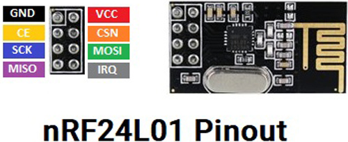
The nRF24L01 is a single chip low-power RF transceiver module. That is why we can configure the module for transmitting and receiving. But nRF24L01 is only capable of doing half-duplex communication for that reason, we can either send or receive data at a time. The nRF24L01 comes with a 2.4GHz RF band and which is legal to use for Industrial, Scientific, and Medical purposes. For better understanding, the pinout of this module is shown below.
The module consumes very low power that is why it is suitable for IoT projects. As this module communicates via SPI, it is very easy to pair with any microcontroller over the SPI bus. Also, this module has a very high transfer speed of 250Kbps to 2Mbps for long-range communication 100m to 1000m.
This is a very cheap module that operates under the 2.4GHz ISM band. It has a maximum throughput of 2Mbps and the signal of this module is encoded with GFSK modulation Technique. As we have mentioned earlier, this module has two variants, the cheaper one does not offer the PA+LNA but the more expensive one offers a built-in PA+LNA that can boost the output signal of this module to 3dBm. This module operates under a supply voltage of 1.9V to 3.6V and consumes only 13.5mA of current and in deep sleep mode, it consumes 26uA. One very interesting fact of this module is that the SPI pins of this module are 5V tolerant so we can directly communicate this module with Arduino without a Logic level converter.
Components Required to Build the nRF24L01 Based Test Circuit
The component required to build this project is very generic and most of these can be found in your local hobby store. A list of required components is given below.
- PIC Microcontroller (PIC18F46K22) - 1
- Arduino Uno/Nano any - 1
- nRF24L01- 1
- 20MHz crystal oscillator for PIC - 1
- 33pf Capacitor - 2
- 4.7k, 100E Resistor - 1
- 10uF and 0.1uF for nRF24L01 Decoupling Capacitor - 2
- PicKit3 Programmer - 1
- Led - 1
- Push Button - 1
- Bread Board
- Jumper wires
- 12V adapter and Breadboard power supply to Power up the PIC and nRF24L01 card module
- MPLAB-X IDE and xc8 compiler.
- Arduino IDE
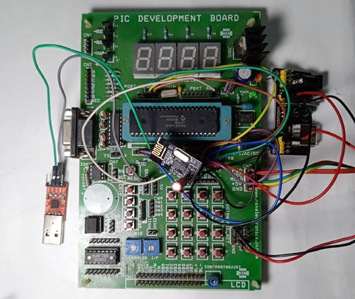
Schematic Used to Connect the nRF24L01 With PIC18F46K22 Microcontroller
The complete schematic diagram to make the PIC18F6K22 based SPI Communication Test Circuit is shown below.

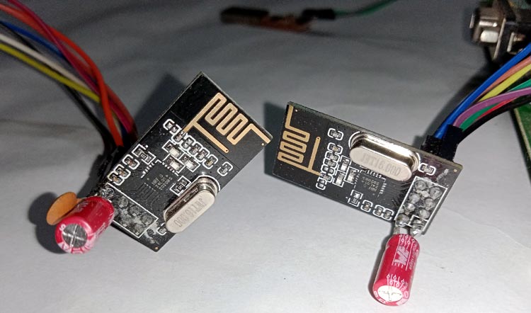
Note: The nRF24L01 module is sensitive to power supply noise. Therefore, it is always a good idea to include a decoupling capacitor in the power supply line. The capacitor can be 10uF and 0.1uF. The 3.3V pin on Arduino boards may not always provide adequate power to the nRF24L01 module. So, it is also a good idea to strengthen the module with an external power source. For our demonstration, we have directly soldered the capacitor onto the pin of the nRF module.
Program to Establish Communication Between nRF24L01 Module with PIC and Arduino Microcontroller
In this project, we use the nRF24L01 library for Arduino to send and receive the data over RF between PIC18 and Arduino. We use the Microchip Code Configurator(MCC) to configure the program for (PIC18F46K22). The complete program can be found at the bottom of this page.
Note: For convenience, we have ported the NRF library from Arduino, and you can get that by click on the download link below.
Code for PIC18F46K22:
Those libraries mentioned above are included at the beginning of the code.
#include "mcc_generated_files/mcc.h"
#include "nrf24_lib.h"
#include <string.h>
Next, we define 2 macros for configuring the application for nRF24L01 Tx operation and Rx operation. We need to change the NRF24L01_TX_EX value to 1 for Tx operation and 0 for Rx operation.
#define NRF24L01_TX_EX  0
#define NRF24L01_RX_EX  !NRF24L01_TX_EX
Next, we define a call back function for Led blink using Timer0 about 1sec time interval. This is our heartbeat indicator LED that will blink in conjunction with a timer. This is an indicator that our system is working properly.
void blink_led() {
LED_Toggle();
}
In the main() function, we call the SYSTEM_Initialize() function to initialize the system peripheral like (INTERRUPT, Pin, Timer0, UART, SPI1) and enable the Global and Peripheral Interrupt.
void main(void)
{
// Initialize the device
SYSTEM_Initialize();
// If using interrupts in PIC18 High/Low Priority Mode you need to enable the Global High and Low Interrupts
// If using interrupts in PIC Mid-Range Compatibility Mode you need to enable the Global and Peripheral Interrupts
// Use the following macros to:
// Enable the Global Interrupts
INTERRUPT_GlobalInterruptEnable();
// Disable the Global Interrupts
//INTERRUPT_GlobalInterruptDisable();
// Enable the Peripheral Interrupts
INTERRUPT_PeripheralInterruptEnable();
// Disable the Peripheral Interrupts
//INTERRUPT_PeripheralInterruptDisable();
After the system initialization, we call the TMR0_SetInterruptHandler() function set the callback function, and then start the Timer0.
TMR0_SetInterruptHandler(blink_led);
TMR0_StartTimer();
After all the initialization, we can start the process with the nRF24L01. At first, we need to initialize the nRF24, for that, we need to call the nrf24_rf_init() function along with the nRF24L01 Operation mode(Tx or Rx) and the RF channel frequency (0-127). After successfully initializing the nRF24, print the current configure nRF24’s Register Maps setting.
#if NRF24L01_TX_EX
ret = nrf24_rf_init(TX_MODE, 115); // Tx mode with 2400+115 Ghz RF frq
#elif NRF24L01_RX_EX
ret = nrf24_rf_init(RX_MODE, 115); // Rx mode with 2400+115 Ghz RF frq
#endif
if (ret == NRF24_INIT_OK) {
    printf("###############################################################\r\n");
    printf("NRF24L01 Initialize successful\r\n");
    nrf24_printf_rf_config();
    printf("###############################################################\r\n");
After initializing the nRF24, we execute the Tx and Rx operation process in a while loop.
● In Tx mode: We create a buffer along with an integer variable value and pass the buffer into the nrf24_send_rf_data() & increment the integer variable value.
#if NRF24L01_TX_EX
    static char val = 0;
    sprintf(bufferTX, "Sending: %d", val);
    nrf24_send_rf_data(bufferTX);
    val++;
    __delay_ms(100);
● In Rx mode: We monitor the nrf24_is_rf_data_available() to get the status that nRF24 receives some data or not. After receiving some data, we call nrf24_read_rf_data() to get the received data into the buffer and print the buffer.
#elif NRF24L01_RX_EX
    while (nrf24_is_rf_data_available()) {
    }
    nrf24_read_rf_data(bufferRX);
    printf("RX data %s\r\n", bufferRX);
    __delay_ms(10);
#endif
Code for Arduino:
On the Arduino side of things, we start our code by including all the required libraries. The library includes RF24 to access nRF24L01 commands, SPI library, and printf library. And we also include some machines that we are going to use to set the module as transmitter and receiver.
//Include Libraries
#include <SPI.h>
#include <nRF24L01.h>
#include <RF24.h>
#include "printf.h"
#define NRF24L01_TX_EX  1
#define NRF24L01_RX_EX  !NRF24L01_TX_EX
Next, we create an instance for the RF24 and we pass on the CE and CSN PIN we also hold the address through which we are going to communicate with the module.
//create an RF24 object
RF24 radio(9, 8);  // CE, CSN
//address through which two modules communicate.
const byte address[6] = {0xe1, 0xe1, 0xe1, 0xe1, 0xe1};
Next, we have our setup function. In the setup function, we initial the serial monitor for debugging and we also set up the NRF24 Radio.
  Serial.begin(115200);
  printf_begin();
  Serial.println(F("\n\rRF24/examples/scanner/"));
  // Setup and configure rf radio
  radio.begin();
  radio.setAutoAck(false);
Now, remember the two macros that we have defined up to. with the help of these macros, you can set up the module as a transmitter or receiver very easily.
#if NRF24L01_TX_EX
  //set the address
  radio.openWritingPipe(address);
  radio.setPALevel(RF24_PA_MIN); //set as: RF24_PA_MIN, RF24_PA_LOW, RF24_PA_HIGH, RF24_PA_MAX
  radio.setDataRate(RF24_2MBPS); //set as: F24_250KBPS, F24_1MBPS, F24_2MBPS ==>250KBPS = longest range
  radio.setChannel(115); //sets channel from 2.4 to 2.524 GHz in 1 MHz increments 2.483.5 GHz is normal legal limit
  radio.setCRCLength(RF24_CRC_8);
  radio.printDetails();
  //Set module as transmitter
  radio.stopListening();
#elif NRF24L01_RX_EX
  radio.openReadingPipe(0, address);
  radio.setPALevel(RF24_PA_MIN); //set as: RF24_PA_MIN, RF24_PA_LOW, RF24_PA_HIGH, RF24_PA_MAX
  radio.setDataRate(RF24_2MBPS); //set as: F24_250KBPS, F24_1MBPS, F24_2MBPS ==>250KBPS = longest range
  radio.setChannel(115); //sets channel from 2.4 to 2.524 GHz in 1 MHz increments 2.483.5 GHz is normal legal limit
  radio.setCRCLength(RF24_CRC_8);
  // Get into standby mode
  radio.startListening();
  radio.stopListening();
  radio.printDetails();
  // Get into standby mode
  radio.startListening();
#endif
Next, we have our loop function. In the loop function, we have taken an array of 32 to which we will store the message and send it over to another module. Now, with the help of the sprint () function, we send one character at a time and we also print the value on the serial monitor window for debugging. And finally, we end our code with a delay of 250ms, at last, this will give us the module additional stability.
void loop()
{
#if NRF24L01_TX_EX
  //Send message to receiver
  char text[32] = {0};
  sprintf(text, "Hello PIC18 %d", val++);
  radio.write(&text, sizeof(text));
  Serial.println(text);
#elif NRF24L01_RX_EX
  //Read the data if available in buffer
  if (radio.available())
  {
    char text[32] = {0};
    radio.read(&text, sizeof(text));
    Serial.println(text);
  }
#endif
delay(250);
}’
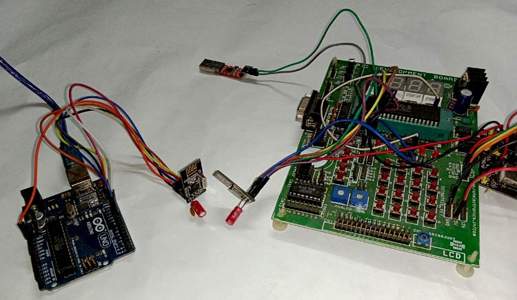
Testing and Debugging the Communication Process
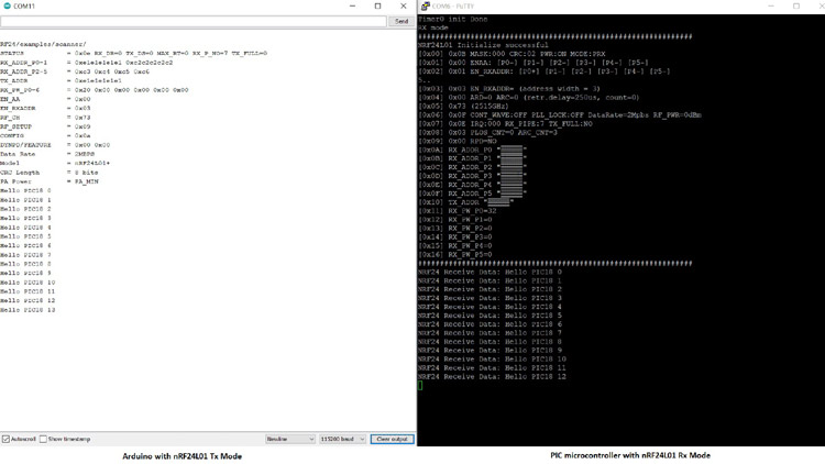
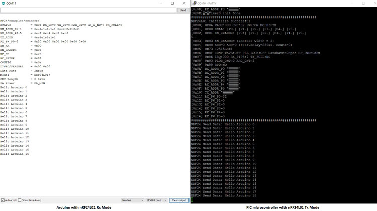
Once the circuit and code were complete, we tested the circuit with the help of the debug log that we have put in our code. As you can see, we have used an Arduino IDE serial monitor to UART converter to log debug data for Arduino UNO, and for the PIC microcontroller, we use a PuTTY serial monitor.
Debugging Log for (Uno as Tx & PIC as Rx):
Once we see the “Hello PIC18 10” message on the Arduino IDE serial monitor. Then we look into the PuTTY serial monitor to verify that the received data message is the same or not at the PIC microcontroller side. The below image show exactly that.
Debugging Log for (Uno as Rx & PIC as Tx):
Once we see the “Hello Arduino 10” message into the PuTTY serial monitor, then we look into the Arduino IDE serial monitor to verify that the received data message is the same or not at the Arduino side.
Comments
Hi, great projec , congrats..
Just a question , I download the library files you guys provided and am having problems with the X8 compiler using the MPlab in the _getch function from the EUSART1 library..I am using the stdio.h file provided by mplab x but still no luck till now.
Another issue also and maybe its related that i cant find the string.h library file that you guys are using in the proyect..could you guys please share it..appreciate it..thx

Great article! Thanks!