
 LoRa Module with Arduino")
It is expected that by 2020 we will have 25 Billion devices connected to the internet. To give you an idea that is more than three times the population of earth today. With the concepts of IoT and Industry 4.0, Connected Vehicles and Smart Cities spreading rapidly, this is most likely to happen. We already have a handful of wireless protocols like BLE, Wi-Fi, Cellular etc, but these technologies were not ideal for IoT sensor nodes since they needed to transmit information to long distance without using much power. This lead to the rise of LoRa Technology, which can perform very-long range transmission with low power consumption.
As ESP modules become synonyms for Wi-Fi applications, this LoRa technology also has caliber to build a vast network like Internet. We previously build many IoT Based projects using ESP8266 and Arduino, here in this article we will learn about LoRa and how to use it with Arduino Development Platform.
What is LoRa?
The term LoRa stands for Long Range. It is a wireless Radio frequency technology introduced by a company called Semtech. This LoRa technology can be used to transmit bi-directional information to long distance without consuming much power. This property can be used by remote sensors which have to transmit its data by just operating on a small battery.
Typically Lora can achieve a distance of 15-20km (will talk more on this later) and can work on battery for years. Remember that LoRa, LoRaWAN and LPWAN are three different terminologies and should not be confused with one another. We will discuss them briefly later in this article.
Understanding LoRa Technology
In any typical IoT solution provided for warehouse management or field monitoring, there will hundreds of Sensors nodes deployed on the field which will monitor the vital parameters and send it to the could for processing. But these sensors should be wireless and should operate on a small battery so that it is portable. Wireless solutions like RF can send data to long distance but requires more power to do so thus cannot be battery operated, while BLE on the other hand can work with very little power but cannot send data to long distance. So this is what brings in the need for LoRa.
In LoRa we can achieve high distance communication without using much power, thus overcoming the drawback of Wi-Fi and BLE communication. But how is it possible? If that is the case why do BLE and RF still exist?
That is because LoRa comes with its own drawbacks. In order to achieve high distance with Low power LoRa compromises on Bandwidth, it operates on very low bandwidth. The maximum bandwidth for Lora is around 5.5 kbps, this means that you will be able to send only small amount of data through LoRa. So, you cannot send Audio or Video through this technology, it works great only for transmitting less information like sensor values. The below chart shows where LoRa lies compared with Wi-Fi, Bluetooth and Cellular devices.
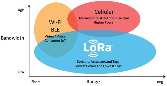
Many people compare LoRa with Wi-Fi or Bluetooth, but these two do not stand anywhere near LoRa. Bluetooth is used to transfer information between two Bluetooth devices and Wi-Fi is used to transfer information between an Access Point (Router) and Station (Mobile). But LoRa technology was primarily not invented to transmit data between two LoRa modules.
You can think of LoRa to be more like cellular communication. Signal from one LoRa Node reaches another Node through a LoRa Gateway as shown in the image below.
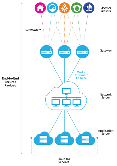
These Gateways then take the information to the internet and finally to the end user through an application interface. Similarly the data from the user will also reach the node through the network server and the Gateway.
A LoRa Node usually operates on a Battery and consists of a Radio Module and Microprocessor. The Microprocessor is used to read the data from the senor and send it in the air through the Radio module which will then be picked up by a LoRa Gateway. The LoRa Gateway also has a Radio Module and a Microprocessor but is normally operated over AC mains since they require more power. A single LoRa Gateway could listen to multiple LoRa nodes, while a single LoRa node could also send information to multiple gateways, this way the information from the node will be picked up gateway without it being lost. When information id is sent from the node to the gateway it is called as uplink and when it is sent from gateway to node it is called as down link.
LoRa falls under the category of LPWAN, where LPWAN stands for Low Power Wide Area Network. It is not just LoRa that can operate on LPWAN, but we also have other technologies like Narrow Band IoT (NB-IOT), Sigfox etc. which are capable of operating in the same LPWAN. Once the technology of LoRa was introduced, it needed certain set of protocols to be followed by all manufactures, so the LoRa alliance was formed which then introduced the LoRaWAN. LoRaWAN is a modified form of LPWAN which specifies the protocol on how LoRa in a physical layer should be used to send and receive data among the nodes, gateways and to the internet.
How much distances can I communicate with LoRa?
The Official Information on LoRa claims that it could achieve a distance of 715km line of sight. That is when there is no obstacle between the Node and Gateway. Few people have even practically achieved communication between 212km Ground to Ground and even upto 702km using weather Balloon.
LoRa SX1278 with Arduino
Enough theory lets actually build it ourselves and check how it is working. Remember the part where I told you that two LoRa modules cannot communicate with each other? Well I lied… Yes, the LoRaWAN Protocol does not allow communication between two LoRa modules, but there is technique called the Radio Head Packet Method which does follow the LoRaWAN protocol but allows us to communicate with two LoRa modules cool right!!. So let’s use two LoRa modules and two Arduino Boards to send data from one board and receive it on the other. We will use Arduino Uno at transmitter side and Arduino Nano at receiving side.
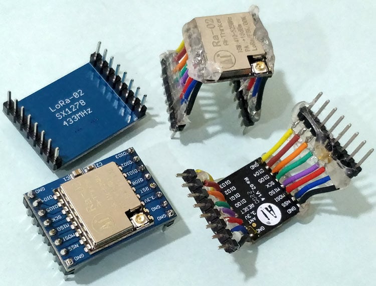
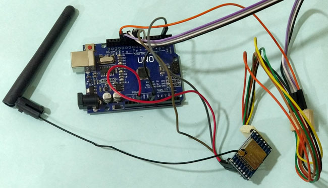
The LoRa module that I am using here is the SX1278 Ra-02 which operates on 433MHz. I am from India and here the unlicensed Frequency range is from 865MHz to 867MHz, so I am not legally allowed to use the 433MHz frequency module for a long time other than for educational purpose. Similarly check the allowed Ranges in your country and make sure you are allowed to use the particular frequency range. LoRa modules do come in different frequency ranges, the most common being the 433MHz, 915MHz and 868MHz. The frequency at which your module works will be mentioned at the back of the module. Also you can either buy LoRa as a module or just the chip. If you are planning to get only the chip then make sure your soldering skills are good since its a delicate job to solder wires to the LoRa chip. I have both the Module and Chip version soldered with wires as shown below.
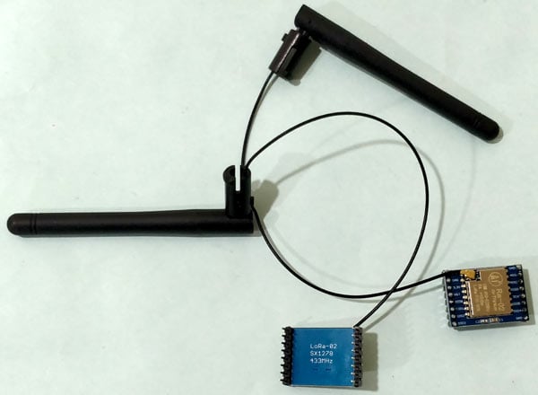
Next important thing to have with your LoRa module is your Antenna. Remember that it is mandatory to operate the LoRa module only with an antenna, else the output transmitting power will damage the Module. I am using a 433Mhz Lora module so my antennas are also rated for 433MHz, you have to select your antenna accordingly. My LoRa module along with antenna is shown below.
Transmitting Side- Connecting LoRa SX1278 with Arduino UNO
For the transmitting side we will use an Arduino UNO with our LoRa module. The circuit diagram to connect the Arduino UNO with LoRa is shown below

The LoRa module consists of 16 pins with 8 pins on each side. Out of these 16 pins, six are used by GPIO pins ranging from DIO0 to DIO5 and four are used by Ground pins. The module operates in 3.3V and hence the 3.3V pin on LoRa is connected to the 3.3v pin on the Arduino UNO board. Then we connect the SPI pin on the LoRa to the SPI pins on Arduino Board as shown above. You can also use the table below to make sure the connection is done correctly
LoRa SX1278 Module | Arduino UNO Board |
3.3V | 3.3V |
Gnd | Gnd |
En/Nss | D10 |
G0/DIO0 | D2 |
SCK | D13 |
MISO | D12 |
MOSI | D11 |
RST | D9 |
I have used connecting wires to make my connection between Arduino UNO and LoRa Module. The setup looks something like this shown below. The whole set-up can is powered by a power bank to make it portable to test the range.
Receiving Side- Connecting LoRa SX1278 with Arduino Nano
For the Receiving side we will use an Arduino Nano with LoRa module. You can use any Arduino board that you have for transmitter and receiver, but make sure you connect them accordingly. The circuit diagram to connect the Arduino Nano with LoRa is shown below

The connections almost remain the same except for one subtle change. The 3.3V pin of the LoRa module is not powered by the Arduino Nano but with an external 3.3V regulator. This is because the on-board regulator on Arduino Nano cannot provide enough current for the LoRa module to operate. Other than this the connections remain the same. I am also pasting a similar table below for your reference.
LoRa SX1278 Module | Arduino Nano Board |
3.3V | - |
Gnd | Gnd |
En/Nss | D10 |
G0/DIO0 | D2 |
SCK | D13 |
MISO | D12 |
MOSI | D11 |
RST | D9 |
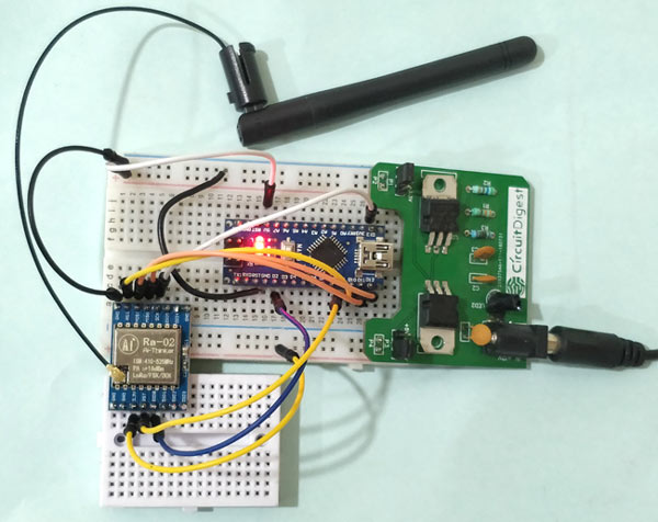
I made the connection on a breadboard and used my trusty old breadboard power supply that we built earlier. Also note that the LoRa modules that I used are not breadboard friendly hence I have used two small breadboard to make the connections as shown below.
Preparing the Arduino IDE for LoRa Wireless Communication
Once the hardware is ready we can move on to the Arduino IDE. To work with LoRa module using Arduino, we already have a well-built LoRa library by Sandeep Mistry. In this article we will just include the Library to our Arduino IDE and use the example sketches with slight modifications to make our LoRa modules communicate between them.
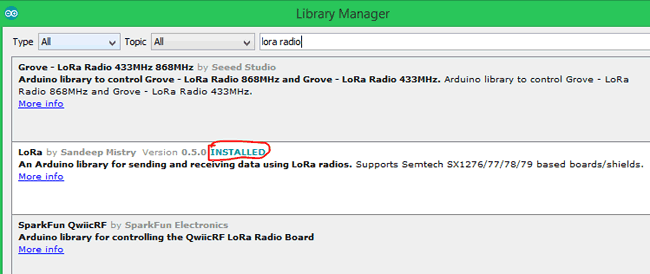
To add the library, open you Arduino IDE and follow Sketch -> Include Library -> Manage Libraries. Then search for “LoRa Radio” and look for the library that was made by Sandeep Mistry and click on install. Wait for the installation to complete and you should see something like this in the end
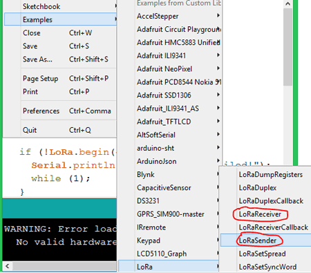
Now restart the Arduino IDE and open the LoRa Example program by using File -> Example -> LoRa and then open both LoRa Receiver and LoRa Sender Program as shown below.
Both the programs are also given at the bottom of the page for your reference. The complete program is self explanatory. The Sender program sends a “hello” for every 5 seconds with a value of counter being incremented. The receiver then receives this and prints on the Serial monitor with the RSSI value.
One important line where you have to make change is the LoRa.begin() function. By default the program has “LoRa.begin(915E6)” meaning it sets the LoRa module to work at 915MHz. That is okay if your module is actually 915MHz, but mine here works on 433MHz frequency as I told earlier, so you have to change it as shown below
LoRa.begin(433E6)
You can visit the library documentation to know what each function in the Library means and how to change it.
Similarly the frequency has to be changed on the Receiver program also. Once the program is ready upload the program on the respective boards after making sure the connections are correct and the antenna is connected to the LoRa module.
LoRa Wireless Communication with Arduino
Once the program is uploaded, open the Serial monitor of both the Arduino boards. The Serial monitor of Sender should show the value that is being sent while the receiver will receive it display it on its serial monitor. The screen should look something like this.
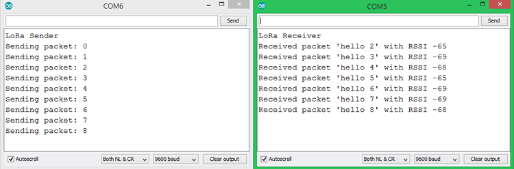
You should also notice the RSSI value of each message received by the LoRa module. The term RSSI stands for Received Signal Strength Indicator. The value will always be in negative, in our case it is around -68. The closer this value is to zero the stronger your signal strength is. For instance if I move both the devices far apart the signal strength will go down.
With this set-up I was able to receive the signal for about 500m with obstacles in between. The value should defiantly be high for Line of sight communication and better antennas. The working can also be found at the video below. Hope you understood the project and enjoyed building something out of it, if you have any problem in getting it to work leave your questions in the comment section and I will try my best answering them.
Complete Project Code
LORA code for Transmitting Side
#include <SPI.h>
#include <LoRa.h>
int counter = 0;
void setup() {
  Serial.begin(9600);
  while (!Serial);
  Serial.println("LoRa Sender");
  if (!LoRa.begin(433E6)) {
    Serial.println("Starting LoRa failed!");
    while (1);
  }
  LoRa.setTxPower(20);

}
void loop() {
  Serial.print("Sending packet: ");
  Serial.println(counter);
  // send packet
  LoRa.beginPacket();
  LoRa.print("hello ");
  LoRa.print(counter);
  LoRa.endPacket();
  counter++;
  delay(5000);
}

LORA code for Receiver Side
#include <SPI.h>
#include <LoRa.h>
void setup() {
  Serial.begin(9600);
  while (!Serial);
  Serial.println("LoRa Receiver");
  if (!LoRa.begin(433E6)) {
    Serial.println("Starting LoRa failed!");
    while (1);
  }
}
void loop() {
  // try to parse packet
  int packetSize = LoRa.parsePacket();
  if (packetSize) {
    // received a packet
    Serial.print("Received packet '");
    // read packet
    while (LoRa.available()) {
      Serial.print((char)LoRa.read());
    }
    // print RSSI of packet
    Serial.print("' with RSSI ");
    Serial.println(LoRa.packetRssi());
  }
}
Comments
Hi, no i did not try with lora ra-01, may be you should consider upgrading to ra-02 since no one realy use ra-01 now. Anyway if you are successful with one packet them you should be able to send otherpackets as well check of your code is looping
hello aswinth
im new at this and am stuck. i have both send and receive set up and send is sending every 5 sec as it should but receive shows "lora receiver" nothing more. if i try to reset and reload occasionally it also shows "receiver packet ' ' with RSSI -164" only one time not every 5 sec. i moved the send and receive right next to each other but same result. sometimes only "lora receiver" alone and sometimes the packet received notation. im 75 and allt the neighborhood 13 year olds are unavailable. can you help??
regards
tom
Hi Tom, I’m having the same problem as you had. Did you manage to resolve your issue?
Thanks in hope.
Robin
Im having exactly the same problem as tom luken, was this issue resolved?
thanks
Robin
hi robin
i needed to ground both sides of my nano...then it worked....
whoknows why
tom
hi aswinth
never mind...i fixed it..operator problem
yhanks
tom
I had the same problem. It appeared that the transmitting side was working, but I received no packets on receiving.
Upon investigation it appears if I changed line 12 the LoRa.begin statement from 915E6 to 433E6 on BOTH receiver and transmitter it works fine. You guys probably have 433 units NOT 915 units. Change the code and it will work
Hi
I am making a project called lora messenge where i can use both sides to send/receive messages. But in your project only one side is used to send could you help me with my project?
Arduino UNO and NANO boards work in 5V and not in 3V3 like the LORA SX1278 module. You cannot directly connect the digital level pins together without using 3V3/5V bidirectional level converters. This wiring is not "electronically clean" with a risk of logical level misinterpreted but especially a destruction of the LORA module.
Take Arduino NANO 33IoT or DUE cards, or ESP32, ESP8266 or STM32 cards that work in 3V3.
I am unable to find antenna for 433MHz LoRa module. Can anyone please provide me the link to purchase LoRa Antenna...
Dear Team may i know how maximum distance you achived please let me know sir based on your answer i move further thank you very much for designing such a wonderful projects
If you new (like me), and using Adafruit LoRa module like the one shown on the Fritsing diagram in the article, THEN wire the Arduino pin10 (yellow wire) to the Adafruit CS pin (NOT EN, like on the picture!). It saves you some time.
Hi. I'm currently making a project using lora modules as a means to get data from a rocket. I would like to ask if is it okay to connect a 900mhz antenna to a 433mhz lora module. if not, why? and what is its effects?
Hi, you have mentioned that you could receive signal with up to 500 meters range . but I saw 10km+ range on Ra-02 chip description. Is it because we are communicating between two modules ? Is there any other method to achieve 10km range without a gateway ?
If you need a 10km range you should try LoraWAN. It is not possible to get this range without a gateway. You can check this out if you want to know how to set-up lorawan gateway in India
https://circuitdigest.com/review/laird-rg186-gateway-setting-up-a-lora-…;
i am trying to interface LoRA Ra 02 with lpc2148 ,please could you guild me how i can start implimenting
If you are just starting with LoRa, then it is advised to start with Arduino, the readily available libraries will make your life a lot easier
how to assign address to slave lora module so that i can communicate with only specific lora module
like in bluetooth we somthing called slave address
my question is how to set address to slave devices?
In a typical lora system, you have a gateway to which all your lora nodes will communicate to. Then on the network layer, you can ignore unwanted messages avoid duplicates etc. You can check out the link below for a better understanding https://circuitdigest.com/review/laird-rg186-gateway-setting-up-a-lora-…
we cant this modul please help me ?
Using the Ra-02 modules with two Arduino Unos. The Transmitter side is sending "Hello", while the receiver side is receiving the Hello, but along with some other garbage values, the receiver side seems to be not functioning properly. Is there an issue with my antenna? or is it the modules?
Please do try to help. This is for a project due soon
hello, I want to ask, how can LoRa Receiver + Esp32 send messages to the cloud using mqtt?
I am very happy if you can help me, and I am very grateful
Can you please the link to buy the antenna and the SMA connector
We can encrypt data, but I could not understand how to make receiver to listen to only particular sender,
I have two transmitter Lora Module transmits some data, consider these as T1 and T2, and one receiver Lora modules R1.
Here receiver module R1 receives data from both transmitter T1 and T2,
So how can we make R1 to receive data from only T1?
Hello.
Im trying to send a packet by LoRa and if the gateway received correctly( by checking CRC), send ACK to sender for next packet part.
Im using ra-02 in 433MHz and my library is LoRa.h.
Is there any function to solve my problem?
and if my sender work in a specific SF(spraeding factor) how the gateway can search for it?
Hello sir,
I am also from India I want to use ra-02 in my final year project.
Would it be okay if I used it in the 433mHz frequency mode for my project as 433Mhz is not license free in india
I tried this combo several times, but the transmitter sends only one time, starts the loop again but stays in the LoRa.endPacket() statement. Any idea what i'm doing wrong?
// Arduino Nano, connected to a RX1278 LoRa-module,
// with a potmeter on A0, sends measured data via LoRa.
#include <SPI.h>
#include <LoRa.h>
int potPin = A0; // Analoge pin waar de potentiometer is aangesloten
int potValue = 0;
void setup() {
Serial.begin(9600);
pinMode(LED_BUILTIN, OUTPUT);
while (!Serial);
if (!LoRa.begin(433E6)) {
Serial.println("LoRa init failed. Check your connections.");
// while (1);
}
LoRa.setTxPower(20);
digitalWrite(LED_BUILTIN, HIGH); // turn the LED on (HIGH is the voltage level)
}
void loop() {
potValue = analogRead(potPin);
LoRa.flush();
Serial.print("Potentiometerwaarde: ");
Serial.println(potValue);
LoRa.beginPacket();
Serial.print("1");
LoRa.print(potValue);
Serial.print("2");
LoRa.endPacket();
Serial.println("3");
digitalWrite(9,1);
digitalWrite(9,0);
digitalWrite(LED_BUILTIN, !digitalRead(LED_BUILTIN)); // turn the LED on (HIGH is the voltage level)
delay(1000); // Vertraging om de waarde niet te vaak te verzenden
}

Hi good works!
I'm trying to use lora ra-01 and arduino nano.Your code works but after one packet others packet doesn't transmit.
Did you try with lora ra-01?