
Self-driving cars are one of the modern world's newest fads. These self-driving cars rely on highly advanced control systems, sensors, actuators, complex algorithms, machine learning systems, and powerful processors. Road lane detection is one of the important things in a self-driving car as it helps the car to keep driving in between the lines. As we all know, Raspberry Pi is a portable development board and we have already built many raspberry pi based projects previously. In our previous tutorial on Autonomous Lane Detection Car using Raspberry Pi and OpenCV, we've already discussed the Hardware assembly, Installing the prerequisites software, Preparing the Motor Driving Code, and Testing the car motors. Now in this tutorial, we are going to write a code to Detect lane lines using OpenCV, Calibrate the Motors with the Lane Detection, and Steer the car according to the lanes detected. In the end, we will also test the car on a test track. So, let’s get started.
Pre-requisites for Autonomous Lane Detection Car
As told earlier, we will be using the OpenCV Library to detect the lanes and for processing the images. So, make sure to install OpenCV Library on Raspberry Pi before proceeding with this tutorial. Also, power your Pi with a 2A adapter and connect it to a display monitor for easier debugging.
This tutorial will not explain how exactly OpenCV works, if you are interested in learning Image processing then check out this OpenCV basics and advanced Image processing tutorials.
Steps involved in Auto Road Lane Detection using Raspberry Pi
Road Lane Detection involves three major steps. The steps are as follows
- Perspective Transformation: The first step for road lane detection is getting the perspective view of the frame. Perspective Transformation can be used to change the perspective of a given image or video to get better insights into the required information. To get the Perspective View of an image, we need to provide the points on the image from which we want to gather information and the points of the output frame inside which we want to display our image.
- Image Thresholding and Canny Edge Detection: Once we get the Perspective view of the road lanes, the next step will be applying the image thresholding and Canny Edge Detection. Image Thresholding is a popular image segmentation technique, that is generally used for separating an object considered as a foreground from its background. In our case, we will use it for road lanes. While Canny Edge detection is used to find the edges in the image.
- Hough Line Transform: The Hough Transform method is used to detect any shape (Shape that can be represented in mathematical form) in an image or video. Here we will use the Hough Line transform method to detect the road lines. To apply the Hough line transformation on an image, first, edge detection of the specific image is desirable.
1. Perspective Transformation
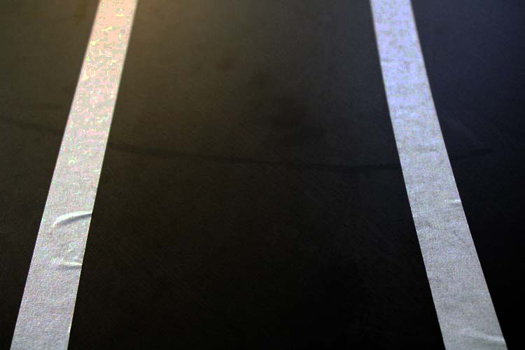
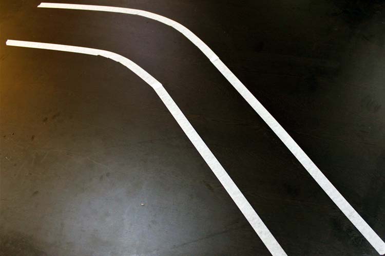
The first step in this Raspberry Pi Lane Detection is to get the Perspective view of the track. For that let’s first take a sample image of the track or you can also perform it directly on the video feed. The original track image is shown below.
Now as mentioned earlier, to get the perspective view of an image, we need to provide the points on the image from which we want to gather information and the points of the output frame inside which we want to display our image. Then these points are stored in NumPy arrays to feed into the Perspective Transformation function.
width, height = 320,240
pts1 = [[0,240], [320,240], [290,30], [30,30]]
pts2 = [[0, height], [width, height], [width,0], [0,0]]
target = np.float32(pts1)
destination = np.float32(pts2)
After getting the points, we get the perspective transform from the two given sets of points and wrap it with the original image using the cv2.getPerspectiveTransform(), and cv2.warpPerspective() function. The syntax for both the functions is given below:
cv2.getPerspectiveTransform(src, dst)
Where:
src: Coordinates of the region of interest for which you want the perspective view.
dst: Coordinates of the output frame inside which you want to display the image.
cv2.warpPerspective(src, dst, dsize)
Where:
src: Source Image
dst: output image that has the size, dsize, and the same type as src.
dsize: the size of the output image
matrix = cv2.getPerspectiveTransform(target, destination)
result = cv2.warpPerspective(frame, matrix, (width, height))
cv2.imshow('Result', result)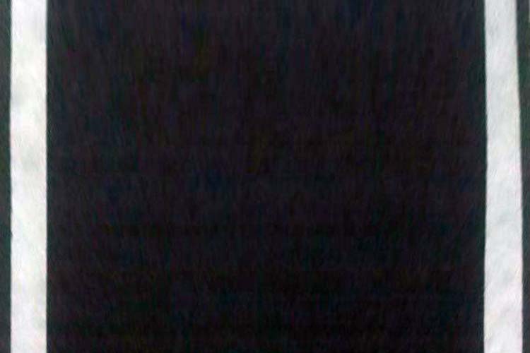
2. Image Thresholding and Canny Edge Detection
Now after the perspective view, we are going to perform the Image Thresholding and Canny Edge Detection. But before doing this, we will first apply the Gray Scale filter to the image. Gray scaling is common in all image processing steps. This speeds up another following process since we have no longer to deal with the color details when processing an image. The image would be transformed something like this when this step is done:
gray = cv2.cvtColor(result, cv2.COLOR_BGR2GRAY)
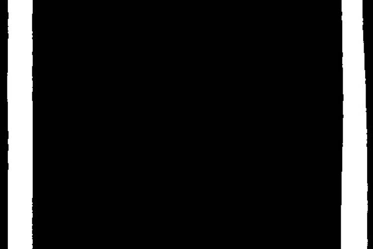
Thresholding is used for separating an object considered as a foreground from its background. The syntax for thresholding is given below:
cv2.inRange(src, lowerb, upperb)
Where:
src: Input Image array (must be in Grayscale).
lowerb: Denotes the lower boundary of the threshold region
upperb: Denotes the upper boundary of the threshold region
threshold = cv2.inRange(gray, 80, 200) # THRESHOLD IMAGE OF GRAY IMAGE
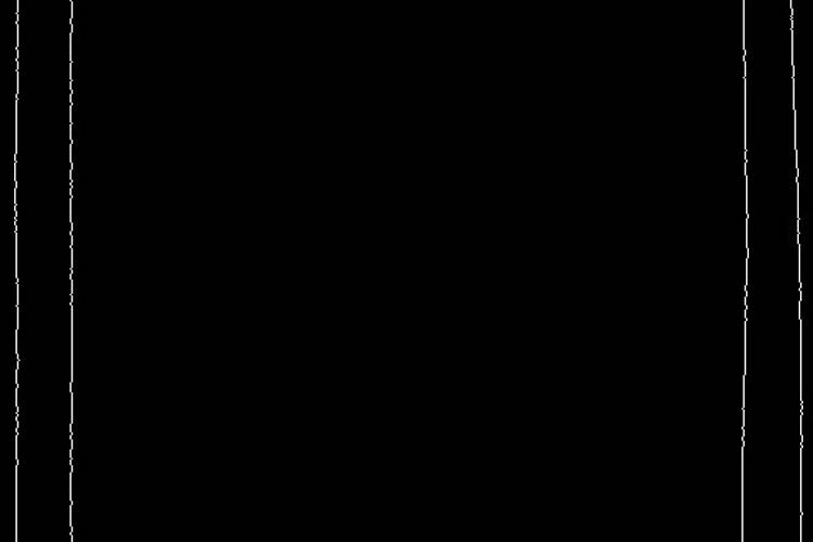
In the next step, we are going to perform edge detection. There are many ways to do it, the easiest and most popular way is to use the canny edge method from OpenCV. The function to do the same is shown below:
edges = cv2.Canny(gray, 1, 100, apertureSize=3)
The syntax will be cv2.Canny(src, thresholdValue 1, thresholdValue 2). Threshold Value 1 and Threshold Value 2 are the minimum and maximum threshold values and src is the input image.
3. Hough Line Transform
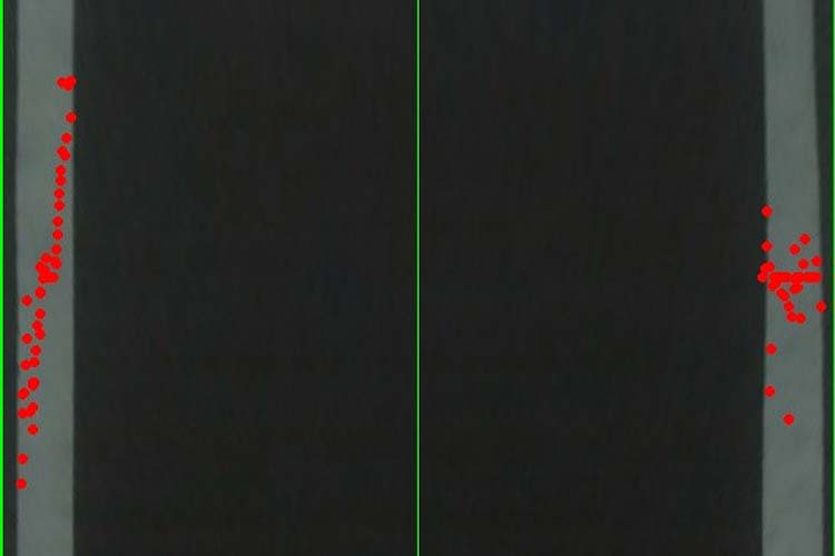
Now after getting the perspective view and applying Thresholding and Canny Edge Detection, in the next step we will be using the Hough Line Transformation to detect the lanes on the track. We will start by finding the center of the frame by using the points of the perspective image that we defined earlier.
firstSquareCenters1 = findCenter((pts2[1][0], pts2[1][1]), (pts2[2][0], pts2[2][1]))
firstSquareCenters2 = findCenter((pts2[3][0], pts2[3][1]), (pts2[0][0], pts2[0][1]))
cv2.line(result, firstSquareCenters1, firstSquareCenters2, (0, 255, 0), 1)
mainFrameCenter = findCenter(firstSquareCenters1,firstSquareCenters2)
After finding the center of the frame, now we will use the Hough Line Transform method to find the lanes on the track. The syntax for the function is shown below:
cv2.HoughLines (image, lines, rho, theta, threshold)
Where:
Image: Input image, should be a binary image so apply threshold edge detection first.
lines: It stores the vector that stores the parameters (r, Φ) of the lines.
rho: Represents the resolution of the parameter r in pixels.
theta: Represents the resolution of the parameter Φ in radians.
threshold: Represents the minimum number of intersections to “detect” a line.
lines = cv2.HoughLinesP(mergedImage,1,np.pi/180,10,minLineLength=120,maxLineGap=250)
After finding the lines, the next step is finding the center of both the lines using the coordinates that we can get from the hough line transform function. After finding the center, we will use the left append and right append function to make the adjustments according to the changes in the positions of the lines.
for line in lines:
            x1,y1,x2,y2 = line[0]
            if 0<=x1 <=width and 0<= x2 <=width :
                center = findCenter((x1,y1),(x2,y2))
                if center[0] < (width//2):
                    center1 = center
                    left.append((x1, y1))
                    left.append((x2,y2))
                else:
                    center2 = center
                    right.append((x1, y1))
                    right.append((x2,y2))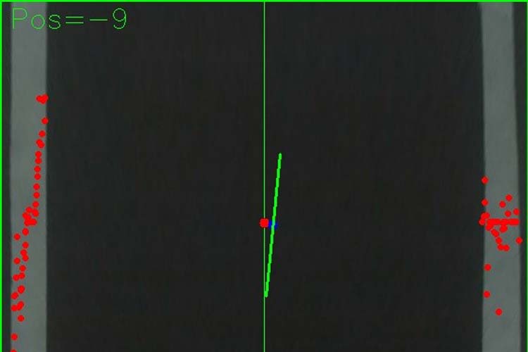
4. Moving the Car
Now that we have found the lines and the center of both the lines, we need to steer the car so that it will stay within the lane lines, even better, we should try to keep it in the middle of the lane. So, if the center coordinates are in middle, the car will go in the forward direction without moving left or right. If the center moves to the right, then the car will turn to the left and vice versa.
if maincenter <= 6 and maincenter > -6:
            mot.frontmiddle()
            speed = 25
        elif maincenter > 6 and frame_counter%10 ==0:
            mot.frontleft()
            speed = 25
            print("Right")
        elif(frame_counter%10 ==0):
            print("Forward")
            mot.forward(speed)
        elif maincenter < -6 and frame_counter%10 ==0:
            mot.frontright()
            speed = 25
            print("left")
Testing the Autonomous Car on Track
Now that we found the lines and a center point to steer the car, let's put the car on the actual track and see how it performs.
The car performs well on straight lines and on slow turns.
But it becomes very hard if there is a sharp turn. That’s because while making sharp turns, one line goes out of the frame and it becomes a bit tricky, as we can’t find the center of the two lines anymore. Apart from that, I have found that the car sometimes bounces left and right between the lane lines and sometimes goes completely out of the lane. This is caused by the varying steering angles, computed from one video frame to the next frame.
We are still working on this project to make it even better and will update it once we found better solutions to the problems discussed above. In meantime, we are waiting to hear your recommendations to make this project better. We hope that this article was good enough to give you some information about how autonomous cars detect road lanes. If you have any questions or suggestions, you can put them in the comment section or can use our forum.
Complete Project Code
houghline.py
import cv2
import numpy as np
import motors as mot
def findCenter(p1,p2):
    center = ((p1[0] + p2[0]) // 2, (p1[1] + p2[1]) // 2)
    return center
def minmax_centerPoints(tergetList,pos):
    if len(tergetList) > 0:
        maximum = max(tergetList, key = lambda i: i[pos])
        minimum = min(tergetList, key = lambda i: i[pos])
        return [maximum,minimum]
    else:
        return None
global  count
def detectedlane1(imageFrame):
    center1= 0
    center2 = 0
    width,height = 320,240
    pts1 = [[0,240],[320,240],[290,30],[30,30]]
    pts2 = [[0, height], [width, height],
                       [width,0], [0,0]]
    target = np.float32(pts1)
    destination = np.float32(pts2)
    # Apply Perspective Transform Algorithm
    matrix = cv2.getPerspectiveTransform(target, destination)
    result = cv2.warpPerspective(frame, matrix, (width,height))
    cv2.imshow('Result', result)
   # cv2.line(imageFrame, (pts1[0][0],pts1[0][1]), (pts1[1][0],pts1[1][1]), (0, 255, 0), 1)
    #cv2.line(imageFrame, (pts1[1][0],pts1[1][1]), (pts1[2][0],pts1[2][1]), (0, 255, 0), 1)
    #cv2.line(imageFrame, (pts1[2][0],pts1[2][1]), (pts1[3][0],pts1[3][1]), (0, 255, 0), 1)
    #cv2.line(imageFrame, (pts1[3][0], pts1[3][1]), (pts1[0][0], pts1[0][1]), (0, 255, 0), 1)
   # cv2.imshow('Main Image Window', imageFrame)
    gray = cv2.cvtColor(result, cv2.COLOR_BGR2GRAY)
    threshold = cv2.inRange(gray, 80, 200)      # THRESHOLD IMAGE OF GRAY IMAGE
    edges = cv2.Canny(gray, 1, 100, apertureSize=3)
    mergedImage = cv2.add(threshold,edges)
    #cv2.line(result, (pts2[0][0], pts2[0][1]), (pts2[1][0], pts2[1][1]), (0, 255, 0), 2)
    #cv2.line(result, (pts2[1][0], pts2[1][1]), (pts2[2][0], pts2[2][1]), (0, 255, 0), 2)
    #cv2.line(result, (pts2[2][0], pts2[2][1]), (pts2[3][0], pts2[3][1]), (0, 255, 0), 2)
    #cv2.line(result, (pts2[3][0], pts2[3][1]), (pts2[0][0], pts2[0][1]), (0, 255, 0), 2)
    firstSquareCenters1 = findCenter((pts2[1][0], pts2[1][1]), (pts2[2][0], pts2[2][1]))
    firstSquareCenters2 = findCenter((pts2[3][0], pts2[3][1]), (pts2[0][0], pts2[0][1]))
  #  print("Centers:", firstSquareCenters1,firstSquareCenters2)
    #cv2.circle (frame, (firstSquareCenters1,firstSquareCenters1),5,(0,0,255),cv2.FILLED)
    cv2.line(result, firstSquareCenters1, firstSquareCenters2, (0, 255, 0), 1)
    mainFrameCenter = findCenter(firstSquareCenters1,firstSquareCenters2)
    lines = cv2.HoughLinesP(mergedImage,1,np.pi/180,10,minLineLength=120,maxLineGap=250)
    centerPoints = []
    left = []
    right = []
    if lines is not None:
        for line in lines:
            x1,y1,x2,y2 = line[0]
            if 0<=x1 <=width and 0<= x2 <=width :
                center = findCenter((x1,y1),(x2,y2))
                if center[0] < (width//2):
                    center1 = center
                    left.append((x1, y1))
                    left.append((x2,y2))
                else:
                    center2 = center
                    right.append((x1, y1))
                    right.append((x2,y2))
                if center1 !=0 and center2 !=0:
                    centroid1 = findCenter(center1,center2)
                    centerPoints.append(centroid1)
        centers = minmax_centerPoints(centerPoints,1)
        laneCenters = 0
        mainCenterPosition = 0
        if centers is not None:
            laneframeCenter = findCenter(centers[0],centers[1])
            #print(mainFrameCenter,laneframeCenter)
            mainCenterPosition = mainFrameCenter[0] - laneframeCenter[0]
            cv2.line(result, centers[0], centers[1], [0, 255, 0], 2)
            laneCenters = centers
           # print(centers)
        return [laneCenters,result,mainCenterPosition]
frame_counter = 0
if __name__ == '__main__':
    cap = cv2.VideoCapture(0)
    cap.set(cv2.CAP_PROP_FRAME_WIDTH,320) # set the width to 320 p
    cap.set(cv2.CAP_PROP_FRAME_HEIGHT,240) # set the height to 240 p
    count = 0
    speed = 0
    maincenter = 0
    while(cap.isOpened()):
        frame_counter = frame_counter+1
        print(frame_counter)
        ret, frame = cap.read()
        if ret == True:
            # Display the resulting frame
            laneimage1 = detectedlane1(frame)
            if laneimage1 is not None:
                maincenter = laneimage1[2]
                cv2.putText(laneimage1[1],"Pos="+str(maincenter),(10, 30), cv2.FONT_HERSHEY_SIMPLEX, 1.0, (0, 255, 0))
                cv2.imshow('FinalWindow',laneimage1[1])
                #print("Position-> "+str(maincenter))
        else:
            cv2.imshow('FinalWindow', frame)
            resizeWindow('FinalWindow',570, 480)
        if maincenter <= 6 and maincenter > -6:
            mot.frontmiddle()
            speed = 25
        elif maincenter > 6 and frame_counter%10 ==0:
            mot.frontleft()
            speed = 25
            print("Right")
        elif(frame_counter%10 ==0):
            print("Forward")
            mot.forward(speed)
        elif maincenter < -6 and frame_counter%10 ==0:
            mot.frontright()
            speed = 25
            print("left")
        #mot.forward(speed)
       # cv2.imshow('Frame', frame)
        key = cv2.waitKey(1)
        if key == 27:
            break
    cap.release()
    cv2.destroyAllWindows()
    mot.stop()motors.py
#MOTOR CLASS
import RPi.GPIO as GPIO
from time import sleep
in1 = 4
in2 = 17
in3 = 18
in4 = 27
en = 22
en2 = 23
temp1 = 1
GPIO.setmode(GPIO.BCM)
GPIO.setup(in1, GPIO.OUT)
GPIO.setup(in2, GPIO.OUT)
GPIO.setup(in3, GPIO.OUT)
GPIO.setup(in4, GPIO.OUT)
GPIO.setup(en, GPIO.OUT)
GPIO.setup(en2, GPIO.OUT)
GPIO.output(in1, GPIO.LOW)
GPIO.output(in2, GPIO.LOW)
GPIO.output(in3, GPIO.LOW)
GPIO.output(in4, GPIO.LOW)
p1 = GPIO.PWM(en, 1000)
p1.stop()
p2 = GPIO.PWM(en2, 1000)
p2.stop()
print("r-run s-stop f-forward b-backward l-low m-medium h-high dm-frontmiddle dr-frontright dl-frontleft e-exit")
def frontmiddle():
    GPIO.output(in3, GPIO.LOW)
    GPIO.output(in4, GPIO.LOW)
    p2.stop()
def frontright():
    GPIO.output(in3, GPIO.LOW)
    GPIO.output(in4, GPIO.HIGH)
    p2.start(100)
def frontleft():
    GPIO.output(in3, GPIO.HIGH)
    GPIO.output(in4, GPIO.LOW)
    p2.start(100)
def forward(speed=50,time=0):
    GPIO.output(in1, GPIO.HIGH)
    GPIO.output(in2, GPIO.LOW)
    p1.start(speed)
    sleep(time)
def backward(speed=50,time=0):
    p1.start(speed)
    GPIO.output(in1, GPIO.LOW)
    GPIO.output(in2, GPIO.HIGH)
    frontmiddle()
    sleep(time)
def stop():
    GPIO.output(in1, GPIO.LOW)
    GPIO.output(in2, GPIO.LOW)
    GPIO.output(in3, GPIO.LOW)
    GPIO.output(in4, GPIO.LOW)
    p1.stop()
    p2.stop()
def fright(speed=50,time=0):
    forward(speed)
    frontright()
    sleep(time)
def fleft(speed=50,time=0):
    forward(speed)
    frontleft()
    sleep(time)
def bright(speed=50,time=0):
    backward(speed)
    frontright()
    sleep(time)
def bleft(speed=50,time=0):
    backward(speed)
    frontleft()
    sleep(time)
if __name__ == '__main__':
stop()Comments
What is the modification that I should do in the event that the path I have: The color of the floor is white and the lines are black؟
Nice work but driver test failed.
Normally you need a signal to noise ratio , SNR > 10 (20 dB) for understanding the feedback with sensor signal conditioning to achieve a high likelihood of error free performance. This is true for any system as long as there are boundaries on speed and lane curve radius, or recognizing speech or balancing an inverted pendulum. The closed loop unity gain and phase margins can be defined for proper steering control such that both steering and wheel drive is defined with values for;
acceleration, velocity, position, timeout, stop on fault criteria, start criteria.
Just as flying a plane has a checklist criteria, there is a need to do the same. Transfer functions are required to define motor current vs acceleration for the given vehicle weight and power available. These can be converted to velocity and position from other parameters. Ultimately to meet a criteria of X %lane position error, you need more lane margin outside the wheels than shown and a wider vision to correct for driving to fast with large position errors and anticipated errors with sharp turns ahead. This can be reduced to mathematical expressions and converted to machine language.
Remember in future to always start to expected results or "specs" in writing a list with "must have limits" and "nice to have limits" for all environmental and system variables assumed. Then list all the assumptions in values to achieve these goals is an iterative process to a solution. e.g. motor voltage, current vs acceleration, velocity and position error for steering angle and wheel velocity. with parameters for lane width,margin and turning radius.vs speed limit.
By the way your steering SNR appeared to be about 0 dB which is why it could not steer as expected. However with compensation for error filtering with feedback values and at least ~30 degrees phase margin and 10 dB gain margin at unity gain frequency, one might expect good results.
If speech was only 0 dB SNR your communication error rate would also be expected to be poor but very low error rate with SNR>= 20 dB. The actual threshold vs SNR for acceptable performance depends on your expectations and ability to avoid unexpected results in your communication relationship with your partner or the lane. (lol)

great project , i can work with you