

Resistors, Inductors and Capacitors are the most commonly used passive components in almost every electronics circuit. Out of these three the value of resistors and capacitors are commonly marked on top of it either as resistor colour code or as numeric marking. Also the resistance and capacitance can also be measured using normal Multimeter. But most of the inductors, especially the ferrite cored and air cored ones for some reason does not seem to have any sort of marking on them. This becomes quite annoying when you have to select the right value of inductor for your circuit design or have salvaged one from an old electronic PCB and wanted to know the value of it.
A forthright solution for this problem is to use an LCR meter which could measure the value of the inductor, capacitor or resistor and display it directly. But not everyone has an LCR meter handy with them, so in this article lets us learn how to use an oscilloscope to measure the value of inductor or capacitor using a simple circuit and easy calculations. Of course if you need a more quick and robust way of doing it you can also build your own LC meter which uses the same technique along with an additional MCU to read the display the value.
Materials Required
- Oscilloscope
- Signal Generator or simple PWM signal from Arduino or other MCU
- Diode
- Known capacitor (0.1uf, 0.01uf, 1uf)
- Resistor (560 ohm)
- Calculator
To measure the value of unknown inductor or capacitor we need to build a simple circuit called the tank circuit. This circuit can also be called as LC circuit or Resonant circuit or Tuned circuit. A tank circuit is circuit in which we will have an inductor and capacitor connected in parallel to each other and when the circuit is powered the voltage and current across it will resonant at a frequency called resonating frequency. Let’s understand how this happens before we move forward.
How does a Tank Circuit work?
As told earlier a typical tank circuit just consists of an inductor and capacitor connected in parallel. The capacitor is a device consisting of just two parallel plates which is capable of storing energy in electric field and an inductor is a coil wounded over a magnetic material which is also capable of storing energy in magnetic field.
When the circuit is powered the capacitor gets charged and then when the power is removed the capacitor discharges its energy into the inductor. By the time capacitor drains its energy into the inductor, the inductor gets charged and would use its energy to push current back into the capacitor in opposite polarity so that the capacitor gets charged again. Remember that inductors and capacitors change polarity when they charge and discharge. This way the voltage and current would swing back and forth creating a resonance as shown in the GIF image above.
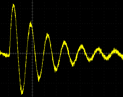
But this cannot happen forever because, every time the capacitor or inductor charges and discharges some energy (voltage) is lost due to the resistance of the wire or as magnetic energy and slowly the magnitude of the resonance frequency would fade away as show in the below waveform.
Once we get this signal on our scope we can measure frequency of this signal which is nothing but the resonant frequency then we can use the below formulae to calculate the value of Inductor or capacitor.
FR = 1 / / 2π √LC
In the above formulae FR is the resonant frequency, and then if we know the value of capacitor we can calculate the value of Inductor and similarly we know the value of inductor we can calculate the value of capacitor.
Set-up for measuring Inductance and Capacitance
Enough theory, now let’s get building the circuit on a breadboard. Here I have an inductor whose value I should find out by using a known value of inductor. The circuit set-up that I am using here is shown below

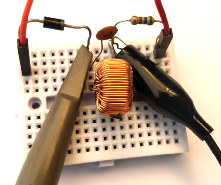
The capacitor C1 and Inductor L1 forms the tank circuit, the Diode D1 is used to prevent the current from entering back into the PWM signal source and the resistor 560 ohms is used for limiting the current through the circuit. Here I have used my Arduino to generate PWM waveform with variable frequency, you can use a function generator if you have one or simply use any PWM signal. The scope is connected across the tank circuit. My hardware set-up looked like below once the circuit was complete. You can also see my unknown torrid core inductor here
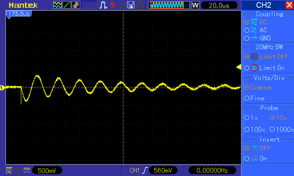
Now power up the circuit using the PWM signal and observe for a resonance signal on the scope. You can try changing the value of capacitor if you do not get a clear resonance frequency signal, commonly 0.1uF capacitor should work for most inductors but you can also try with lower values like 0.01uF. Once you get the resonance frequency it should look something like this.
How to Measure Resonance Frequency with oscilloscope?
For some people the curve will appear as such, for other you might have to tweak around a bit. Make sure scope probe is set to 10x since we need the decoupling capacitor. Also set time division at 20us or less and then decrease the magnitude to less than 1V. Now try increasing the frequency of the PWM signal, if you do not have a waveform generator then try decreasing the value of the capacitor until you notice the resonance frequency. Once you get the resonance frequency put the scope in single seq. mode to get a clear waveform like the one shown above.
After getting the signal we have to measure the frequency of this signal. As you can see the magnitude of the signal dies away as time increases so we can select any one complete cycle of the signal. Some scope might have a measure mode to do the same, but here I will show you how to use the cursor. Place the first cursor line on the starting of the sine wave and the second cursor on the ending of the sine wave as shown below to measure the period of the frequency. In my case the time period was as highlighted in the picture below. My scope also displays the frequency but for learning purpose just consider the time period you can also use the graph lines and time division value to find the time period if your scope does not display it.
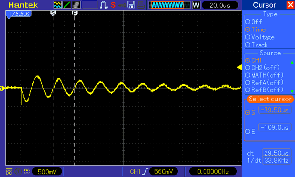
We have measured only the time period of the signal, to know the frequency we can simply use the formulae
F = 1/T
So in our case the value of time period is 29.5uS which is 29.5×10⁻⁶. So the value of frequency will be
F = 1/(29.5×10-6) = 33.8 KHz
Now we have the resonant frequency as 33.8×10³ Hz and the value of capacitor as 0.1uF which is 0.1 ×10⁻⁶ F substituting all this in the formulae we get
FR = 1 / 2π √LC
33.8×103  = 1 / 2π √L(0.1 x 10⁻⁶)
Solving for L we get
L = ( 1/(2π x 33.8 x 103)2 / 0.1×10-6
   = 2.219×10-4
    = 221 ×10-6

 L ~= 220 uH
So, the value of unknown inductor is calculated to be 220uH, similarly you can also calculate the value of capacitor by using a known inductor. I also tried it with few other known inductor values and they are seemed to work just fine. You can also find the complete working in the video attached below.
Hope you understood the article and learnt something new. If you have any problem in getting this to work for you, leave your questions in the comment section or use the forum for more technical help.
Comments
Why did you choose the 560ohm
Why did you choose the 560ohm value?

What is the typical working value/characteristics of the diode D1?