
We all know of the wired doorbell systems which require wires and suitable outlets for it to work satisfactorily. As the wired doorbell system needs complicated wiring, it requires an experienced person to get the work done and it does not do good, in both working and appearance. Another problem with it is that, if you want to install a wired doorbell system for an existing house, it needs more effort and time for the installation. Due to the temperature and humidity, and other environmental factors, wires are damaged and will lead to a short circuit. This is where the wireless doorbell system gets into the picture. Even though the cost of the wireless Doorbell system is more, when compared to the wired doorbell system, the regular maintenance for the wireless Doorbell system is low when compared with the wired doorbell system, which requires an experienced person for maintenance purposes. When it comes to installation, wireless doorbell systems are very simple to install and requires no experience person for installation. In addition to this, wireless doorbell systems have additional features like camera, video recorder, etc and look stylish, and it can be easily installed in any part of the house as it is completely wireless.
In this project, we are going to build a Wireless Doorbell using Arduino. We will have a button which when pressed will wirelessly play a melody of our choice to indicate someone is at the door. For wireless connectivity, we will use the 433 MHz RF module. In general, the RF module must always be accompanied by a decoder and encoder module, but in place of the decoder and encoder module, we can also use a microcontroller such as Arduino which we are using in this tutorial. If you want to build a simple wired Doorbell you can check this Doorbell using 555 IC tutorials to build one.
Hardware Required:
- RF module
- Arduino
- Buzzer
- Push-button
- Breadboard
- Connecting wires
433 MHz RF Module:
For our Arduino based Wireless Doorbell, we will be using the 433 MHz Wireless RF modules. An RF module, which is a Radio Frequency module consists of two modules, one which receives the data called receiver, and the one which transmits the data called transmitter.

Learn more about the RF transmitter and receiver by following the link.
RF Transmitter:
A transmitter consists of a SAW resonator, which is tuned to 433MHz frequency, a switching circuit, and a few passive components.
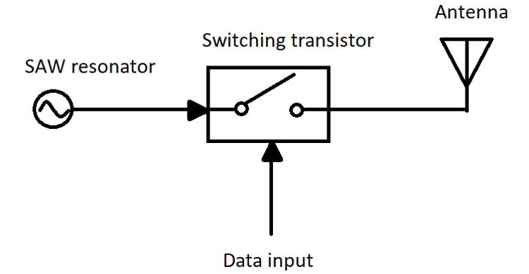
When the input to the data pin is HIGH, the switch will act as a short circuit and the oscillator runs which produces a fixed amplitude carrier wave and a fixed frequency for some period of time‘t’. When the input to the data pin is low, the switch acts as an open-circuit and the output will be zero. This is also known as Amplitude shift keying (ASK). We will discuss more on this later in this article
Receiver Circuit:
An RF receiver is a simple circuit that consists of an RF tuned circuit, an amplifier circuit, and a phase lock loop circuit.
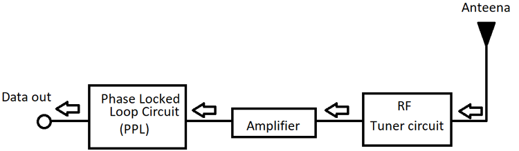
An RF tuner is used to tune the circuit to a particular frequency, which needs to meet the transmitted frequency. An amplifier circuit is used to amplify a particular frequency from all other signals and to increase the sensitivity of the particular frequency.
Phase Lock Loop Circuit:
A phase lock loop circuit (PLL) is a circuit that is used in types of equipment in which we want a highly stable frequency from a low-frequency reference signal. A PLL is a negative feedback system that consists of a voltage-controlled oscillator and a phase comparator connected in such a way that the oscillator frequency always matches the input signal as shown below.
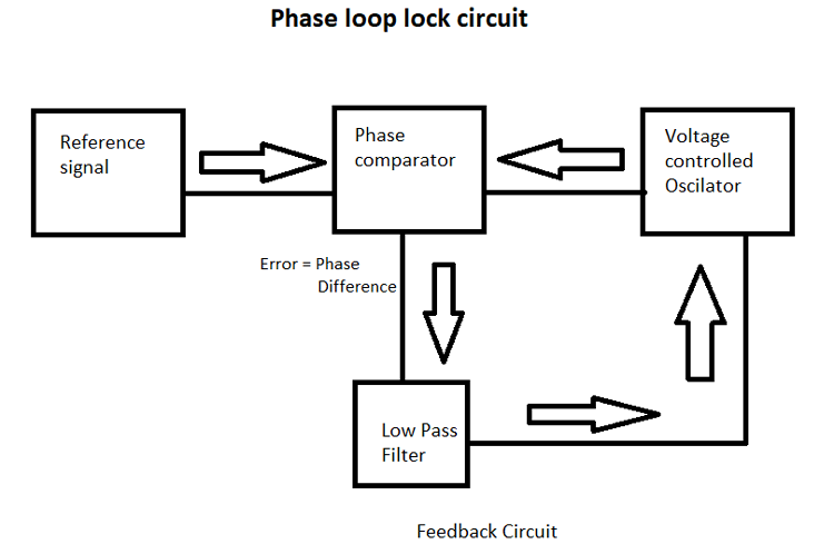
In the PLL circuit two signals i.e. from the reference signal and the signal from the voltage-controlled oscillator (VCO), is given as inputs to the phase detector and the output from the phase detector the difference between both the inputs, and this output is the phase difference of both the signals. This output contains frequency components, which are the sum and difference of the signals. So, this output is given as input to the low pass filter, which allows only low frequencies, and doesn’t allow the high-frequency signals to pass through. The output of the low pass filter is fed to a voltage-controlled oscillator (VCO), and this input acts as a value to the VOC, which must be changed to decrease the phase difference between both the signals. The change in the VCO takes place until the phase difference is minimal, or the output of the phase detector has a constant error output. This results in the loop lock situation.
With all these components, the receiver receives the signal from the antenna which is then tuned by RF tuned circuit and this weak signal is amplified using OP-Amp, and this amplified signal is further used as input to PLL, which makes the decoder to lock onto the incoming digital bits which gives an output which is less in noise.
Modulation:
Modulation is a process of converting data into electrical signals, and these modulated signals are used for transmission. We modulate the signals so that we can separate the necessary signal from other signals. Without modulation, all the signals having the same frequencies will get mixed, which will lead to error. There are many types of modulation the popular ones are Analog Modulation, Digital Modulation, Pulse Modulation, and Spread Spectrum.
Out of these the most popular one used in a wireless transmission is digital modulation. The popular Digital modulation techniques are Amplitude Shift Keying, Frequency Shift Keying, Phase Shift Keying, Orthogonal Amplitude Modulation.
Amplitude Shift Keying (ASK) Modulation:
In Amplitude Shift key modulation, the sinusoidal carrier will keep on generating continuous high-frequency carrier, and the signal which is to be modulated will be in the binary sequence, and these signals make the input to the switching circuit to be either high or low.
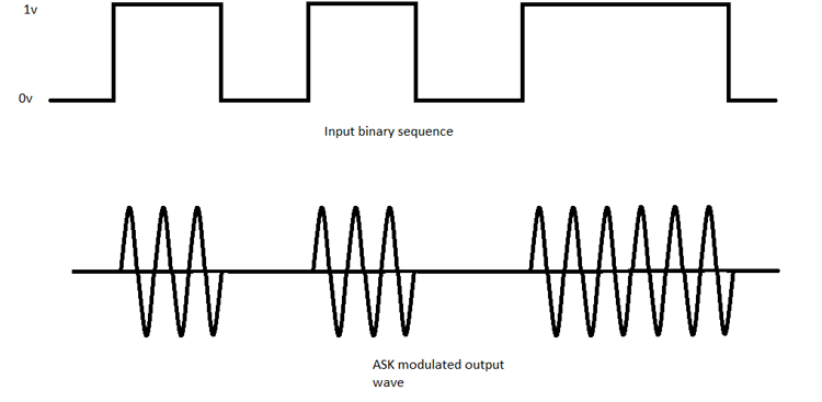
As shown in the above figure, when the input is low, the switch will act as an open circuit, and the output will be zero. When the input to the switch is high, the output will be the carrier signal.
Arduino RF Transmitter Circuit Diagram
Our wireless doorbell project will require a transmitter and receiver circuit each with its own Arduino board. The Circuit diagram for Doorbell Transmitter is shown below

The Arduino pin 5 is connected to the one end of the doorbell switch, and the other end of the switch is connected to the supply voltage. A pull-down resistor of 10kohm is connected to pin 5 as shown in the fig. Pin 11 is connected to the data pin of the transmitter module. Vcc is connected to the supply voltage, and the ground pin of the transmitter module is grounded.
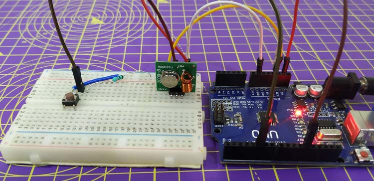
In here I used a breadboard for connecting the modules, and a push-button is used as a doorbell switch.
Arduino RF Receiver Circuit Diagram
Similarly, on the receiver side, we need to use another Arduino board with the RF receiver module. Then the Arduino Doorbell Receiver circuit also has a buzzer is to play some melody when the button is pressed.

Here, we connect pin 7 of the Arduino to the buzzer positive terminal, and the negative terminal is grounded. A supply voltage of VCC is given to the receiver module, and the GND pin of the module is connected to the ground. The out pin of the receiver module is connected to the 12th pin of the Arduino.
The receiver module consists of 4 pins in which one pin is grounded, and another one pin is for giving VCC supply, and the remaining two pins are used for data transfer. In the above diagram, a buzzer is connected to the digital 7th pin of the Arduino, and the 12th pin of the Arduino is connected to the receiver module output pin.
Arduino Transmitter Code Explanation
The complete code for the Arduino transmitter part is given at the bottom of this page. The explanation of the code is as follows.
These are the header files which are needed to be included to send or receive the data using the RF module. These libraries make the connection between the Arduino and the module simple. Without these, you have to manually write the code for connecting the RF module with the Arduino. An object is created “driver” to access the commands used for sending and receiving the data. You can download the Radio Head Library for Arduino from Github.
#include <RH_ASK.h>
#include <SPI.h> // Not actually used but needed to compile
RH_ASK driver;
Serial.begin() is used to find whether the RF transmitter module is working or not and I have initialized the PIN 5 (digital pin 5) as an Input pin and this acts as a door-bell switch.
void setup()
{
   Serial.begin(9600); // Debugging only
   pinMode(5,INPUT);
This code is used to print the message “init failed” when the RF TX module does not initialize at starting of the program and this run only ones.
   if (!driver.init())
        Serial.println("init failed");
The if function checks whether the pin is logic HIGH or LOW, i.e. if the doorbell switch is on the state or in an off state. The pointer msg contains the message which we want to send through a transmitter. One note is that we must know the number of characters we need to send. This will help in writing the receiver code.
   if(digitalRead(5)==HIGH){
 const char *msg = "a";
The strlen() command checks the length of the message, which is 1 in this case. The driver.send() commands sends the data to the tx module which are converted into waves. The command driver.waitPacketSent() is used to wait until the data is sent.
driver.send((uint8_t *)msg, strlen(msg));
driver.waitPacketSent();
Arduino Receiver Code Explanation
The Receiver program is also given at the end of this page below the Transmitter code or it can be downloaded from here. You can directly use it with your hardware; the code explanation is as follows.
These are the header files which are needed to be included to send or receive the data using the RF module. These libraries make the connection between the Arduino and the RF module simple. Without these, you have to manually write the code for connecting the RF module with the Arduino.
#include <RH_ASK.h>
#include <SPI.h> // Not actually used but needed to compile
These are the header files that are created for the code to equate the values of frequency to a particular note and get the note values to get the musical tone. If you want to know more about pitches.h or how to play the melody with Arduino and buzzer you can refer to this Melody using Tone() Function tutorial.
#include "pitches.h" //add Equivalent frequency for musical note
#include "themes.h" //add Note vale and duration
An object is created “driver” to access the commands used for sending and receiving the data.
RH_ASK driver;
To print messages in the serial monitor. Then the if condition checks if the initialization is failed or not.
void setup()
{
    Serial.begin(9600);      // Debugging purpose
  if (!driver.init())
         Serial.println("init failed");
     else
        Serial.println("done");
This whole code deals with the notes, pitches, and duration to be taken to the required melody
void Play_Pirates()
{
  for (int thisNote = 0; thisNote < (sizeof(Pirates_note)/sizeof(int)); thisNote++) {
    int noteDuration = 1000 / Pirates_duration[thisNote];//convert duration to time delay
    tone(8, Pirates_note[thisNote], noteDuration);
    int pauseBetweenNotes = noteDuration * 1.05; //Here 1.05 is tempo, increase to play it slower
    delay(pauseBetweenNotes);
    noTone(8); //stop music on pin 8
    }
}
The command uint8_t buf[1] initializes the buf as an unsigned integer of length 8 bits, and the size of the buf variable is 1, as I told you before that we should how many bits we sent and getting the length of the buf variable in binary form.
void loop()
{
        uint8_t buf[1];
    uint8_t buflen = sizeof(buf);
This code checks whether we received the correct data and if the received signal is correct it plays the song.
    if (driver.recv(buf, &buflen)) // Non-blocking
      Serial.println("Selected -> 'He is a Pirate' ");
      Play_Pirates();
      Serial.println("stop");

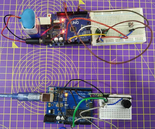
Wireless Arduino Doorbell Working
The transmitter module, along with the Arduino is connected near the door, and the receiver module, along with Arduino, can be installed in any part of the room. When someone presses the switch, it sends the high pulse to the 5th pin of Arduino, which is connected near the door along with the transmitter module. In our Receiver code, we wrote a command- digitalRead(5), this command makes the Arduino, to keep on reading this pin. When this pin gets HIGH, Arduino transmits data through the transmitter, and these signals are received by the receiver. The Arduino, which is connected to a buzzer, reads these signals, and when the desired data is received, the if function is satisfied, and the code will initiate the function, Play_Pirates() and the music will start to play.
The complete working of Arduino based wireless Doorbell project can be found in the video linked at the bottom of this page. Hope you understood the project and enjoyed learning something useful, if you have any questions please leave them in the comment section. For other technical quires use the forums.
Complete code is given below or it can be downloaded from this link.
Complete Project Code
Doorbell Transmitter Code
// ask_transmitter.pde
// -*- mode: C++ -*-
// Simple example of how to use RadioHead to transmit messages
// with a simple ASK transmitter in a very simple way.
// Implements a simplex (one-way) transmitter with an TX-C1 module

#include <RH_ASK.h>
#include <SPI.h> // Not actually used but needed to compile

RH_ASK driver;
// RH_ASK driver(2000, 2, 4, 5); // ESP8266 or ESP32: do not use pin 11


void setup()
{
    Serial.begin(9600);   // Debugging only
    pinMode(5,INPUT);
    if (!driver.init())
         Serial.println("init failed");
}

void loop()
{
    if(digitalRead(5)==HIGH){
    const char *msg = "a";
    driver.send((uint8_t *)msg, strlen(msg));
    driver.waitPacketSent();
    delay(200);
    }
}

Doorbell Receiver Code
#include <RH_ASK.h>
#include <SPI.h> // Not actualy used but needed to compile
#include "pitches.h" //add Equivalent frequency for musical note
#include "themes.h" //add Note vale and duration

RH_ASK driver;

void setup()
{
    Serial.begin(9600); // Debugging only

    if (!driver.init())
         Serial.println("init failed");
     else
        Serial.println("done");
}

void Play_Pirates()
{
  for (int thisNote = 0; thisNote < (sizeof(Pirates_note)/sizeof(int)); thisNote++) {

    int noteDuration = 1000 / Pirates_duration[thisNote];//convert duration to time delay
    tone(8, Pirates_note[thisNote], noteDuration);

    int pauseBetweenNotes = noteDuration * 1.05; //Here 1.05 is tempo, increase to play it slower
    delay(pauseBetweenNotes);
    noTone(8); //stop music on pin 8
    }
}

void loop()
{
    uint8_t buf[1];
    uint8_t buflen = sizeof(buf);

    if (driver.recv(buf, &buflen)) // Non-blocking
    {
      Serial.println("Selected -> 'He is a Pirate' ");
      Play_Pirates();
      Serial.println("stop");
  }
}
Comments
Project works but has some
Project works but has some bugs. Buzzer should be connected to pin 8 and GND. The output from the receiver goes to pin 11.
regards
Dan SQ5DN

By the Transmitter you say: Pin 11 is connected to the data pin of the transmitter module.
Is not market in the schematic. Is it connected or not?
By the Reciever you say: Here, we connect pin 7 of the Arduino to the buzzer positive terminal. But in the schematic is on the pin D5
you say: The out pin of the receiver module is connected to the 12th pin of the Arduino.
Here I have a problem see your picture from 433 MHz RF Module, 4 pins, the first is VCC the last one GND, the two in the middle I dont now.
In jour foto from the Reciever I see the Gray is the VCC and the Green is the GND and i Black go to pin D8. Wer is the Black connected, on the second or the third pin from the module?
In the code from the Reciever you say: noTone(8); //stop music on pin 8. But there is nothing conneted on pin D8