

The ESP Controllers from Espressif are becoming a widely popular choice for IoT based designs. There are many kinds of ESP modules and development boards already available in the market, among which NodeMCU is the most popular one. Apart from that, ESP-12E, ESP01 are also popular choices. But if you want to make your design more flexible and compact, chances are that we have to design our own ESP module from the chip level, instead of directly using a readily available module. In this article, we will learn how to design a circuit and PCB for using the ESP controllers (ESP8285) directly without using a module.
In this project we have used ESP8285 because it is a very interesting little chip. It's a tiny SoC (System on Chip), with IoT (Internet of Things) and deep sleep capabilities. It has the same power as his big brother ESP8266 and as a bonus, it comes with a built-in 1MB flash memory with a lot of GPIO’s. You can also use ESP8266 as an alternative and most of the things discussed in this article will still be the same.
In a previous article, I have shown you how you can design your own PCB antenna for 2.4GHz, using the same ESP8285 chip as an example. You can read that article to learn about antenna design for ESP8266/ESP8285.
So in this article, I will cover how all the circuits work and finally there will be a video explaining it all. I have also covered in detail the complete procedure to design and order the PCB boards from PCBWay for our ESP module design.
Introduction to ESP8285
If you do not know about this versatile ESP8285 chip, here is a quick explanation with a feature list. ESP8285 is a small chip with built-in 1M flash and ram, it's quite similar to the ESP8286, ESP-01 module but the internal flash memory makes it much more compact and cheaper.
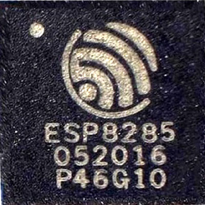
This chip houses Tensilica's L106 Diamond 32-bit core processor and the same goes for the ESP8266 too, that's why all the code for the ESP8266 can be flashed directly to this chip without any modifications, and it has the same network stack as the ESp8266 dose.
The ESP8285 integrates antenna switches, RF balun, power amplifier, low noise receive amplifier, filters, and power management modules. The compact design minimizes the PCB size, and it requires minimal external circuitries. If you want to learn more about this IC, you can always check the datasheet of ESP8285 of the device at Espressif Systems.
ESP Development Board Circuit Diagram
The circuit is very simple and I have broken it down for better understanding. The below ESP schematic shows the whole circuit, as you can see there are eight functional blocks, I will go through each one and explain every block.

ESP8285 SOC:
At the heart of the project is the ESP8285 SoC, all the GPIOs and other necessary connections are defined here.

Power Filter: There are 7 power pins on this IC, first is the power pin for the ADC and IOs. I have shorted them together, and use a 47uF power filter capacitor, and a 0.1uF decoupling capacitor to filter the 3.3V DC input.
PI Filter: The PI filter is one of the most important blocks of this design because it's responsible for powering the RF amplifier and the LNA, any internal or external noise can be descriptive for this section, So for that, the RF section will not work. That's why the low pass filter for the LNA section is very crucial. You can learn more about PI filters by following the link.
Crystal Oscillator: The 40MHz crystal oscillator serves as the clock source for the ESP8285 SoC, and the 10pF decoupling capacitors were added as recommended by the datasheet.
LNA Section: Another most important section of this circuit is the LNA section; this is where the PCB antenna gets connected to the physical pin of the ESP. As recommended by the datasheet, a 5.6pF capacitor is used, and it should work just fine as the matching circuit. But I have added two placeholders for two inductors as if in case the matching circuit dissent works, I can always put some inductors in, to tweak the values to match the antenna impedance.
The LNA section also has two PCB jumpers with a UFL connector. The PCB antenna is set by default, but if your application requires a little more range, you can desolder the PCB jumper and short the jumper for the UFL connector, and you can connect an external antenna just like that.
Battery Input Connector:
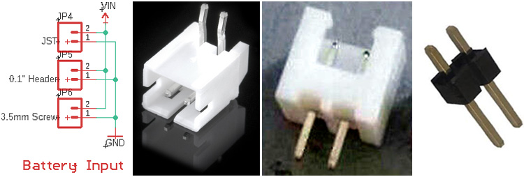
You can see above, I have put three types of battery connectors in parallel because if you were unable to find one, you can always put another one.
GPIO Headers and the Programming Headers:
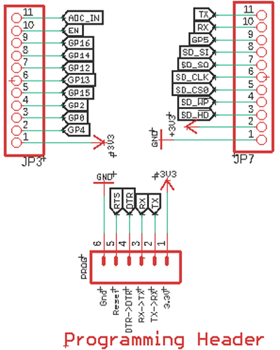
The GPIO headers are there to access the GPIO pins and the programming header is there to flash the main Soc.
Auto Reset Circuit:
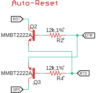
In this block, two NPN transistors, MMBT2222A forms the auto-reset circuit when you push the upload button in the Arduino IDE, the python tool gets a call, this python tool is the flash tool for the ESP devices, this pi tool gives the signal to the UART converter to reset the board while holding the GPIO pin to ground. After that, the upload and verification process begins.
Power LED, On-Board LED, and the Voltage Divider:
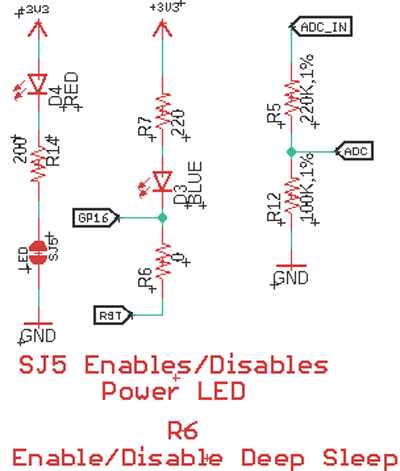
Power LED: The power LED has a PCB jumper If you are using this board as for battery-powered application, you can DE solder this jumper to save quite a bit of power.
Onboard LED: Many dev-boards in the market have an onboard LED, and this board is no exception; the GPIO16 of the IC is connected to an onboard led. Alongside that, there is a placeholder for a 0 OHMs resistor by populating the 0 Ohms resistor, you are connecting GPIO16 to the reset, and as you may know, this is a very important step to put an ESP in deep sleep mode.
Voltage Divider: As you may know, the maximum input voltage of the ADC is 1V. So, to change the range of the input to 3.3V, the voltage divider is used. The configuration is so made that you can always add a resistor in series with the pin to change the Range to 5V.
HT7333 LDO:
An LDO or Low Dropout Voltage Regulator is used to regulate the voltage to ESP8285 from a battery with minimum power loss.
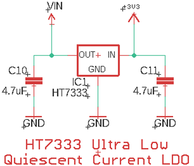
The maximum input voltage of the HT7333 LDO is 12V and it's used to convert the battery voltage to 3.3V, I chose this HT7333 LDO because it's a device with a very low quiescent current. The 4.7uF decoupling capacitors are used to stabilize the LDO.
Push-button for Programming Mode:
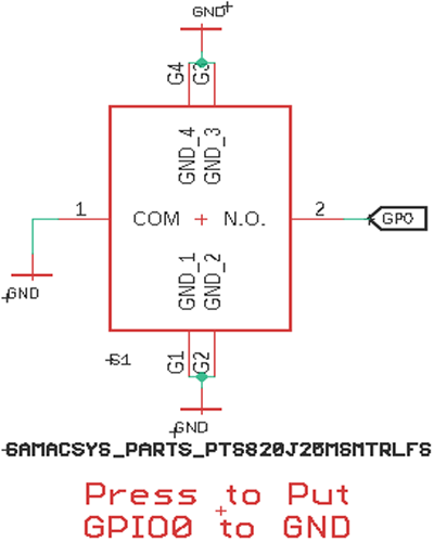
The push-button is connected to GPIO0, if your UART converter doesn't have an RTS or DTR pin, you can use this push-button to manually pull the GPIO0 to ground.
Pullup and Pulldown Resistors:
The pullup and pulldown resistors are there as recommended by the datasheet.
Other than that, many design norms and guidelines were followed while designing the PCB. If you want to know more about that, you can find that in the hardware design guide for the ESP8266.
Fabricating our ESP8285 Dev Board
The schematic is done, and we can proceed with laying out the PCB. We have used Eagle PCB design software to make the PCB, but you can design the PCB with your preferred software. Our PCB design looks like this when it's completed.
Now, that our Design is ready, it is time to get the PCBs fabricated using. To do so, simply follow the steps below:
Ordering PCB from PCBWay
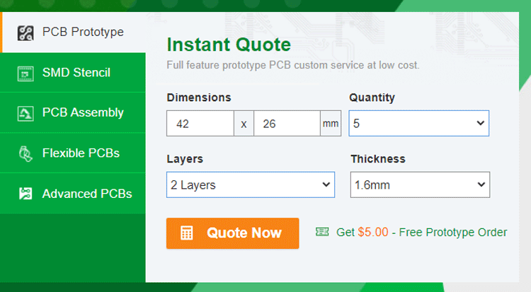
Step 1: Get into https://www.pcbway.com/, sign up if this is your first time. Then, in the PCB Prototype tab, enter the dimensions of your PCB, the number of layers, and the number of PCB you require.
Step 2: Proceed by clicking on the ‘Quote Now’ button. You will be taken to a page where to set a few additional parameters like the Board type, Layers, Material for PCB, Thickness, and More, most of them are selected by default, if you are opting for any specific parameters, you can select it in hear.
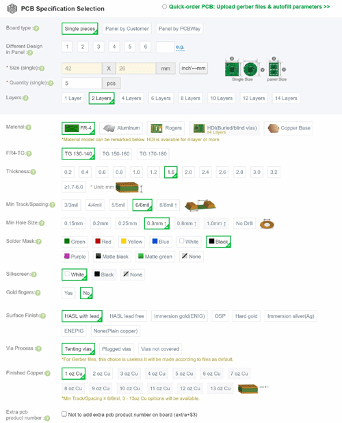
As you can see, we needed our PCBs black! so, I have selected black in the solder mask color section.
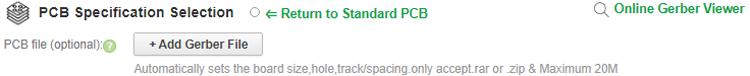
Step 3: The final step is to upload the Gerber file and proceed with the payment. To make sure the process is smooth, PCBWAY verifies if your Gerber file is valid before proceeding with the payment. This way, you can be sure that your PCB is fabrication friendly and will reach you as committed.
Assembling and Programing the ESP8285 Board
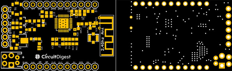
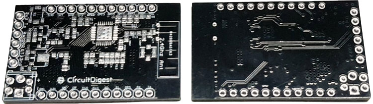
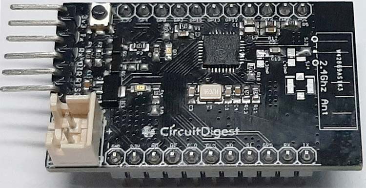
After a few days, we received our PCB in a neat package box, and the PCB quality was good as always. The top layer and the bottom layer of the board is shown below:
After receiving the board, I immediately started soldering the board. I have used a hot air soldering station and a lot of solder flux to solder the main CPU, and other components on the PCB are soldered via a soldering iron. The assembled module is shown below.
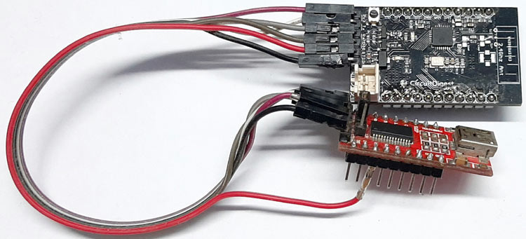
Once that is done, I have connected my trusty FTDI module to test the board by uploading a sketch, The connected pins and an image of the board shown below:
ESP8285 Dev Board FTDI Module
3.3V -> 3.3V
Tx -> Rx
Rx -> Tx
DTR -> DTR
RST -> RST
GND -> GND
Once, all the necessary connections are completed, I have set up the Arduino IDE by selecting the Generic ESP8285 Board from Tools > Board > Generic ESP8285 Module.

Testing with a Simple LED Blink Sketch
Next, it's time to test the board by blinking an LED, for that, I have used the following code:
/*
ESP8285 Blink
Blink the blue LED on the ESP828285 module
*/
#define LED_PIN 16 //Define blinking LED pin
void setup() {
  pinMode(LED_PIN, OUTPUT); // Initialize the LED pin as an output
}
// the loop function runs over and over again forever
void loop() {
  digitalWrite(LED_PIN, LOW); // Turn the LED on (Note that LOW is the voltage level)
  delay(1000); // Wait for a second
  digitalWrite(LED_PIN, HIGH); // Turn the LED off by making the voltage HIGH
  delay(1000); // Wait for two seconds
}
The code is very simple, first I have defined the LED pin for this board, and it's on GPIO 16. Next, I have set that pin as an output in the setup section. And finally, in the loop section, I have turned on and off the pin with a one-second delay in between.
Testing Webserver Sketch on ESP8285
Once that was working fine, it's time to test the HelloServer sketch from the ESP8266WebServer Example. I am using an ESP8266 example because most of the code is compatible with the esp8285 chip. The example code can also be found at the bottom of this page.
This code is very simple too, First, we need to define all the necessary libraries,
#include <ESP8266WiFi.h>
#include <WiFiClient.h>
#include <ESP8266WebServer.h>
#include <ESP8266mDNS.h>
next, we need to enter the name and password of the hotspot.
#ifndef STASSID
#define STASSID "your-ssid"
#define STAPSK  "your-password"
#endif
const char* ssid = STASSID;
const char* password = STAPSK;
Next, we need to define the ESP8266WebServer object. The example here defines it as a server (80) the (80) is the port number.
Next, we need to define a pin for an LED in my case it was pin no 16.
const int led = 16;
Next, the handleRoot() Function is defined. This function will be called when the call on the IP address from our browser.
void handleRoot() {
  digitalWrite(led, 1);
  server.send(200, "text/plain", "hello from esp8266!");
  digitalWrite(led, 0);
}
Next is the setup function, hear we have to define all the necessary parameters like-
pinMode(led, OUTPUT); // we have defined the led pin as output
Serial.begin(115200);  // we have started a serial connection with 115200 baud
WiFi.mode(WIFI_STA); // we have set the wifi mode as station
WiFi.begin(ssid, password); then we begin the wifi connection
Serial.println(""); // this line gives an additional space
while (WiFi.status() != WL_CONNECTED) {
    delay(500);
    Serial.print(".");
  } /* in the while loop we are testing the connection status one the ESP is able to connect to the hotspot the loop will brake*/
Serial.println("");
Serial.print("Connected to ");
Serial.println(ssid);
Serial.print("IP address: ");
Serial.println(WiFi.localIP());
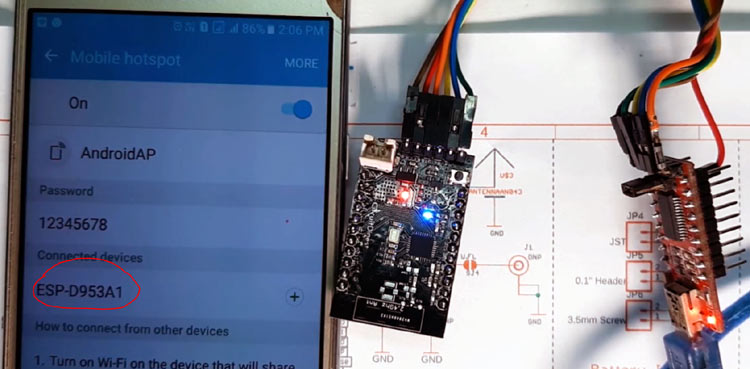
Next, we are printing the name and the IP address of the connected SSID to the serial monitor window.
server.on("/", handleRoot); // the on methode of the server object is called to handel the root function
server.on("/inline", []() {
   server.send(200, "text/plain", "this works as well");
  });
// again we have called the on methode for the /inline example
server.begin(); // next we start the server with the begin methode
Serial.println("HTTP server started"); // and finally we print a statement in the serial monitor.
} // which marks the end of the setup function
void loop(void) {
  server.handleClient();
}
In the loop function, we have called the handleClient() methods to operate the esp properly.
Once this was done, the ESP8285 board took some time to get connected to the webserver and successfully worked as expected which marked the end of this project.
The complete working of the board can also be found at the video linked below. I hope you enjoyed this article and learned something new out of it. If you have any doubt, you can ask in the comments below or can use our forums for detailed discussion.
Complete Project Code
#include <ESP8266WiFi.h>
#include <WiFiClient.h>
#include <ESP8266WebServer.h>
#include <ESP8266mDNS.h>
#ifndef STASSID
#define STASSID "your-ssid"
#define STAPSK  "your-password"
#endif
const char* ssid = STASSID;
const char* password = STAPSK;
ESP8266WebServer server(80);
const int led = 16;
void handleRoot() {
  digitalWrite(led, 1);
  server.send(200, "text/plain", "hello from esp8266!");
  digitalWrite(led, 0);
}
void setup(void) {
  pinMode(led, OUTPUT);
  digitalWrite(led, 0);
  Serial.begin(115200);
  WiFi.mode(WIFI_STA);
  WiFi.begin(ssid, password);
  Serial.println("");
  // Wait for connection
  while (WiFi.status() != WL_CONNECTED) {
    delay(500);
    Serial.print(".");
  }
  Serial.println("");
  Serial.print("Connected to ");
  Serial.println(ssid);
  Serial.print("IP address: ");
  Serial.println(WiFi.localIP());
  server.on("/", handleRoot);
  server.on("/inline", []() {
    server.send(200, "text/plain", "this works as well");
  });
  server.begin();
  Serial.println("HTTP server started");
}
void loop(void) {
  server.handleClient();
}
Fantastic post! I was hoping to understand more about the layout you went with but I was unable to download the gerber file. Could you share a new link? Thomas