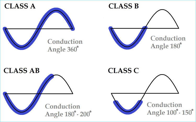
In electronics, Amplifier is the most commonly used circuit device with huge application possibilities. In Audio related electronics pre-amplifier and power amplifiers are two different types of amplifier systems which are used for sound amplification related purposes. But, other than this application-specific purpose, there are huge differences in various types of amplifiers, mainly in Power Amplifiers. So here we will explore different classes of amplifiers along with their advantages and disadvantages.
Classifications of Amplifiers using Letters
Amplifier classes are the identity of amplifier’s performance and characteristics. Different type of power amplifiers gives different responses when passing current through them. According to their specifications, Amplifiers are assigned different letter or alphabets which represent their classes. There are different classes of amplifiers starting from A, B, C, AB, D, E, F, T etc. Out of those classes most commonly used audio amplifiers classes are A, B, AB, C. Other Classes are modern amplifiers which use switching topologies and PWM (Pulse Width Modulation) technique to drive the output load. Sometimes, improved version of traditional classes are assigned a letter to classify them as a different class of amplifier, like class G amplifier is a modified Amplifier class of Class B or Class AB amplifier.
Classes of the amplifier represent the input cycle proportion when the current is passed through amplifier. The input cycle is the conduction angle derives from the sinusoidal wave conduction in the amplifier input. This conducting angle is highly proportional with the Amplifiers on time during a full cycle. If the amplifier is always ON during a cycle, the conduction angle will be 360 degrees. So, if an amplifier provides 360-degree conduction angle, then the amplifier used complete input signal and the active element conducted through the 100% time period of a complete sinusoidal cycle.
Below, we will demonstrate traditional Power amplifier classes ranging from Class A, B, AB and C, and also demonstrate Class D amplifier which is widely used in switching designs. These classes are not only used in Power Amplifier but also used in Audio Amplifiers circuits.
Class A Amplifier
Class A amplifier is a high gain amplifier with high linearity. In case of Class A amplifier, the conduction angle is 360 degree. As we stated above, a 360-degree conduction angle means the amplifier device remains active for the entire time and use complete input signal. In the below image an ideal class A amplifier is shown.
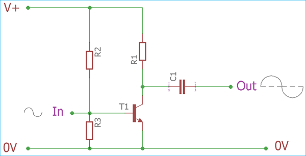
As we can see in the image, there is one active element, a transistor. The bias of the transistor remains ON all of the time. Due to this never turn off feature, Class A amplifier provides better high frequency and feedback loop stability. Other than these advantages, Class A amplifier is easy to construct with a single-device component and minimum parts count.
Despite the advantages and high linearity, certainly, it has many limitations. Due to continuous conducting nature, the class A amplifier introduce high power loss. Also, due to high linearity, Class A amplifier provides distortion and noises. The power supply and the bias construction need careful component selection to avoid unwanted noise and to minimize the distortion.
Because of high power loss in Class A amplifier, it emits heat and requires higher heat sink space. The efficiency is very poor in Class A amplifiers, theoretically, the efficiency varies between 25 to 30 % if used with the usual configuration. The efficiency can be improved using inductively coupled configuration but the efficiency in such case is not more than 45-50%, thus it is only suitable for low signal or low power level amplification purposes.
Class B Amplifier
The Class B amplifier is a bit different from the Class A. It is created using two active devices which conduct half of the actual cycle, ie 180 degrees of the cycle. Two devices provide combined current drive for the load.
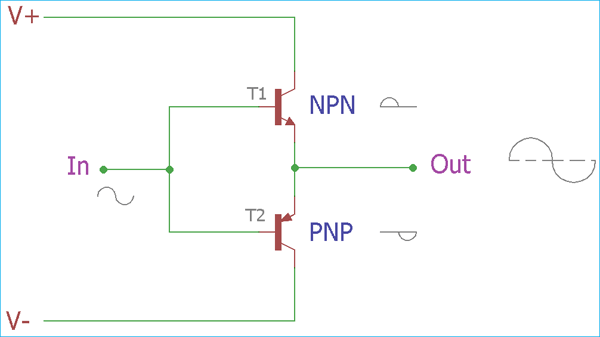
In the above image, an Ideal Class B amplifier configuration has been shown. It consists two active devices which get biased one by one during the positive and negative half cycle of sinusoidal wave and thus the signal gets pushed or pulled to the amplified level from both positive and negative side and combine the result we get complete cycle across the output. Each device turned on or became active half of the cycle, and due to this the efficiency gets improved, comparing to 25- 30% efficiency of Class A amplifier, it provides more than 60% efficiency theoretically. We can see each device input and output signal graph in the below image. The efficiency is not more than 78% for Class B amplifier. The heat dissipation is minimized in this class providing a low heat sink space.
But, this class also have limitation. A very profound limitation of this class is the crossover distortion. As two devices provides each half of the sinusoidal waves which are combined and joined across the output, there is a mismatch (cross over) in the region, where two halves are combined. This is because when one device complete the half cycle, the other one needs to provide the same power almost at the same time when other one finish the job. It is difficult to fix this error in class A amplifier as during the active device the other device remains completely inactive. The error provides a distortion in the output signal. Due to this limitation, it is a major fail for precision audio amplifier application.
Class AB Amplifier
An alternate approach to overcome the cross-over distortion, is to use the AB amplifier. Class AB amplifier uses intermediate conduction angle of both Classes A and B, thus we can see the property of both Class A and Class B amplifier in this AB class of amplifier topology. Same as class B, it has the same configuration with two active devices which conducts during half of the cycles individually but each device biased differently so they do not get completely OFF during the unusable moment (crossover moment). Each device does not leave the conduction immediately after completing the half of the sinusoidal waveform, instead they conduct a small amount of input on another half cycle. Using this biasing technique, the crossover mismatch during the dead zone is dramatically reduced.
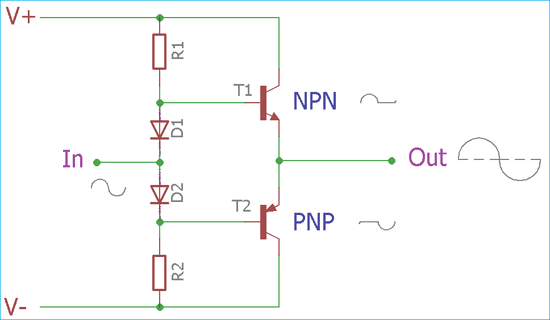
But in this configuration, efficiency is reduced as the linearity of the devices is compromised. The efficiency remains more than the efficiency of typical Class A amplifier but it is less than the Class B amplifier system. Also, the diodes need to be carefully chosen with the exact same rating and need to be placed as close as possible to the output device. In some circuit construction, designers tend to add small value resistor to provide stable quiescent current across the device to minimize the distortion across the output.
Class C Amplifier
Apart from the Class A, B, and AB amplifier, there is another amplifier Class C. It’s a traditional amplifier which works differently than the other amplifiers classes. Class C amplifier is tuned amplifier which works in two different operating modes, tuned or untuned. The efficiency of Class C amplifier is much more than the A, B, and AB. Maximum 80% efficiency can be achieved in radio frequency related operations
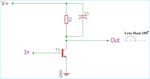
Class C amplifier uses less than 180-degree conduction angle. During the untuned mode, the tuner section is omitted from the amplifier configuration. In this operation, Class C amplifier also gives huge distortion across the output.
When the circuit is exposed to a tuned load, the circuit clamps the output bias level with the average output voltage equal to the supply voltage. The tuned operation is called as clamper. During this operation, the signal gets its proper shape and the center frequency became less distorted.
In typical uses, Class C amplifier gives 60-70% efficiency.
Class D Amplifier
Class D amplifier is a switching amplifier which uses Pulse Width Modulation or PWM. The conduction angle is not a factor in such case as the direct input signal is changed with a variable pulse width.
In this Class D amplifier system, the linear gain is not accepted as they work just like a typical switch which have only two operations, ON or OFF.

Before processing the input signal, the analog signal is converted into a pulse stream by various modulation techniques and then it is applied to the amplifier system. As the pulses duration is related with the analog signal it is again reconstructed using low pass filter across the output.
Class D amplifier is the highest power efficient amplifier class in the A, B, AB, and C and D segment. It has smaller heat dissipation, so small heatsink is needed. The circuit requires various switching components like MOSFETs which has low on resistance.
It is a widely used topology in digital audio players or controlling the motors as well. But we should keep in mind that It is not a Digital converter. Although, for higher frequency, Class D amplifier is not a perfect choice as it has bandwidth limitations in few cases depending on the low pass filter and converter module capabilities.
Other Amplifier Classes
Other than the Traditional amplifiers, there are few more classes, which are class E, Class F, Class G, and H.
Class E amplifier is a highly efficient power amplifier which uses switching topologies and works in radio frequencies. A single pole switching element and the tuned reactive network is the main component to use with the class E amplifier.
Class F is high impedance amplifier in respect of the harmonics. It can be driven using square wave or sine wave. For the sinusoidal wave input, this amplifier can be tuned using an inductor and can be used to increase the gain.
Class G use rail switching to decrease the power consumption and to improve efficiency performance. And Class H is the further improved version of Class G.
Additional classes are special purpose amplifier. In some cases, the letters are provided by the manufacturer for signifying their proprietary design. One best example is Class T amplifier which is a trademark for a special type of switching Class D amplifier, used for Tripath’s amplifier technologies which is a patented design.


Great analysis