
If you have ever visited large scale manufacturing companies, the first thing you will notice is that they are all automated. Soft Drink Industries and Chemical industries have to constantly measure and quantify the liquids that they are handling during this automation process, and the most common sensor used to measure the flow of a liquid is a Flow Sensor. By using a flow sensor with a microcontroller like Arduino, we can calculate the flow rate, and check the volume of liquid that has passed through a pipe, and control it as required. Apart from manufacturing industries, flow sensors can also be found in the agriculture sector, food processing, water management, mining industry, water recycling, coffee machines, etc. Further, a water flow sensor will be a good addition to projects like Automatic Water Dispenser and Smart Irrigation Systems where we need to monitor and control the flow of liquids.
In this project, we are going to build a water flow sensor using Arduino. We will interface the water flow sensor with Arduino and LCD, and program it to display the volume of water, which has passed through the valve. For this particular project, we are going to use the YF-S201 water flow sensor, which uses a hall effect to sense the flow rate of the liquid.
Components Required
- Water Flow Sensor
- Arduino UNO
- LCD (16x2)
- Connector with internal threading
- Connecting wires
- Pipe
YFS201 Water Flow Sensor
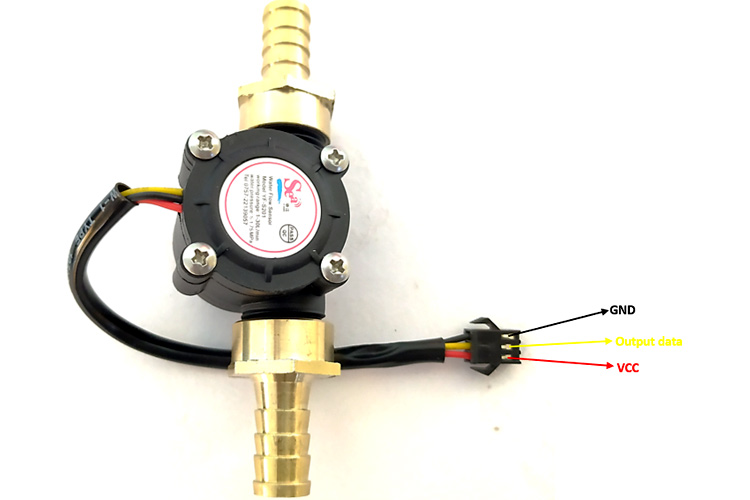
The sensor has 3 wires RED, YELLOW, and BLACK as shown in the figure below. The red wire is used for supply voltage which ranges from 5V to 18V and the black wire is connected to GND. The yellow wire is used for output(pulses), which can be read by an MCU. The water flow sensor consists of a pinwheel sensor that measures the quantity of liquid that has passed through it.
The working of the YFS201 water flow sensor is simple to understand. The water flow sensor works on the principle of hall effect. Hall effect is the production of the potential difference across an electric conductor when a magnetic field is applied in the direction perpendicular to that of the flow of current. The water flow sensor is integrated with a magnetic hall effect sensor, which generates an electric pulse with every revolution. Its design is in such a way that the hall effect sensor is sealed off from the water, and allows the sensor to stay safe and dry.
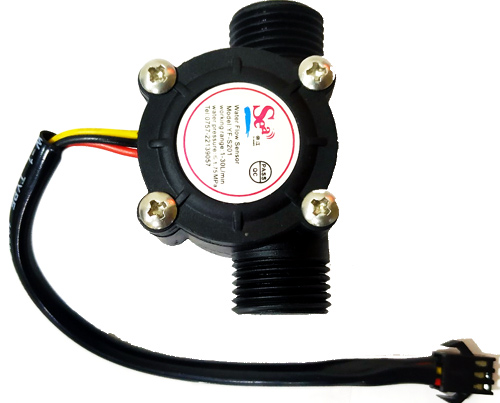
The picture of the YFS201 sensor module alone is shown below.
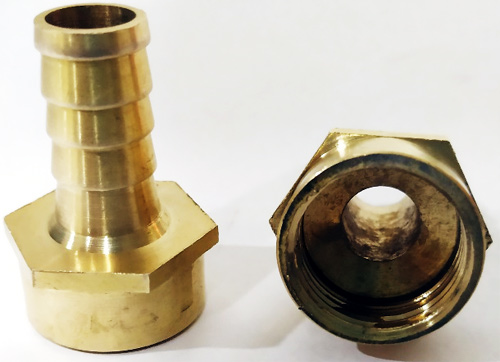
To connect with the pipe and water flow sensor, I used two connectors with a female thread as shown below.
According to YFS201 Specifications, the maximum current it draws at 5V is 15mA, and the working flow rate is 1 to 30 liters/minute. When the liquid flows through the sensor, it makes contact with the fins of the turbine wheel, which is placed in the path of the flowing liquid. The shaft of the turbine wheel is connected to a hall effect sensor. Due to this, whenever water flows through the valve it generates pulses. Now, all we have to do is to measure the time for the pluses or to count the number of pulses in 1 second and then calculate the flow rates in liter per hour (L/Hr) and then use simple conversion formula to find the volume of the water which had passed through it. To measure the pulses, we are going to use Arduino UNO. The pic below shows you the pinout of the water flow sensor.
Circuit Diagram
The water flow sensor circuit diagram is shown below to interface a water flow sensor and LCD (16x2) with Arduino. If you are new to Arduino and LCDs, you can consider reading this Interfacing Arduino and LCD Article.

The connection of the water flow sensor and LCD(16x2) with the Arduino is given below in table format. Note that the pot is connected in between 5V and GND and pot’s pin 2 is connected with the V0 pin of the LCD.
|
S.NO |
Water Flow sensor pin |
Arduino Pins |
|
1 |
Red Wire |
5V |
|
2 |
Black |
GND |
|
3 |
Yellow |
A0 |
|
S.No |
LCD |
Arduino |
|
1 |
Vss |
GND(ground rail of breadboard) |
|
2 |
VDD |
5V (Positive rail of the breadboard) |
|
3 |
For connection with V0 check the above note |
|
|
4 |
RS |
12 |
|
5 |
RW |
GND |
|
6 |
E |
11 |
|
7 |
D7 |
9 |
|
8 |
D6 to D3 |
3 to 5 |
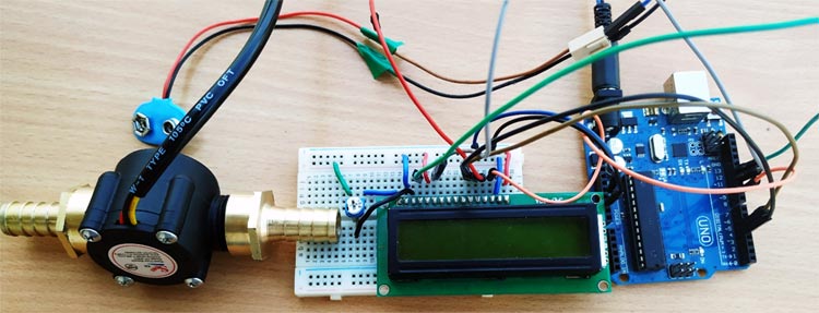
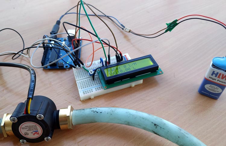
I used a breadboard, and once the connection was done as per the circuit diagram shown above, my testing set-up looked something like this.
Arduino Water Flow Sensor Code
The complete water flow sensor Arduino code is given at the bottom of the page. The explanation of the code is as follows.
We are using the header file of the LCD, which eases our interfacing the LCD with Arduino, and the pins 12,11,5,4,3,9 are allotted for data transfer between LCD and Arduino. The sensor's output pin is connected to pin 2 of Arduino UNO.
volatile int flow_frequency; // Measures flow sensor pulses
// Calculated litres/hour
 float vol = 0.0,l_minute;
unsigned char flowsensor = 2; // Sensor Input
unsigned long currentTime;
unsigned long cloopTime;
#include <LiquidCrystal.h>
LiquidCrystal lcd(12, 11, 5, 4, 3, 9);
This function is an interrupt service routine and this will be called whenever there is an interrupt signal at pin2 of Arduino UNO. For every interrupt signal, the count of the variable flow_frequency will be increased by 1. For more details on the interrupts and their working, you can read this article on Arduino interrupts.
void flow () // Interrupt function
{
   flow_frequency++;
}
In the void setup, we tell the MCU that the pin 2 of the Arduino UNO is used as INPUT by giving command pinMode(pin, OUTPUT). By using attachInterrupt command, whenever there is a rise in the signal at pin 2, the flow function is called. This increases the count in the variable flow_frequency by 1. The current time and cloopTime are used for the code to run in every 1 second.
void setup()
{
pinMode(flowsensor, INPUT);
digitalWrite(flowsensor, HIGH);
Serial.begin(9600);
lcd.begin(16, 2);
attachInterrupt(digitalPinToInterrupt(flowsensor), flow, RISING); // Setup Interrupt
lcd.clear();
lcd.setCursor(0,0);
lcd.print("Water Flow Meter");
lcd.setCursor(0,1);
lcd.print("Circuit Digest");
currentTime = millis();
cloopTime = currentTime;
}
The if function ensures that for every one second the code inside it runs. In this way, we can count the number of frequencies produces by the water flow sensor per second. The flow rate pulse characteristics from the datasheet are given that frequency is 7.5 multiplied by flow rate. So the flow rate is frequency / 7.5. After finding flow rate which is in liters/minute, divide it by 60 to convert it into liter/sec. This value is added to the vol variable for every one second.
void loop ()
{
   currentTime = millis();
   // Every second, calculate and print litres/hour
   if(currentTime >= (cloopTime + 1000))
   {
    cloopTime = currentTime; // Updates cloopTime
    if(flow_frequency != 0){
      // Pulse frequency (Hz) = 7.5Q, Q is flow rate in L/min.
      l_minute = (flow_frequency / 7.5); // (Pulse frequency x 60 min) / 7.5Q = flowrate in L/hour
      lcd.clear();
      lcd.setCursor(0,0);
      lcd.print("Rate: ");
      lcd.print(l_minute);
      lcd.print(" L/M");
      l_minute = l_minute/60;
      lcd.setCursor(0,1);
      vol = vol +l_minute;
      lcd.print("Vol:");
      lcd.print(vol);
      lcd.print(" L");
      flow_frequency = 0; // Reset Counter
      Serial.print(l_minute, DEC); // Print litres/hour
      Serial.println(" L/Sec");
        }
The else function works when there is no output from the water flow sensor within the given time span.
    else {
      lcd.clear();
      lcd.setCursor(0,0);
      lcd.print("Rate: ");
      lcd.print( flow_frequency );
      lcd.print(" L/M");
      lcd.setCursor(0,1);
      lcd.print("Vol:");
      lcd.print(vol);
      lcd.print(" L");
    }
Arduino Water Flow Sensor Working
In our project, we connected the water flow sensor to a pipe. If the output valve of the pipe is closed, the output of the water flow sensor is zero (No pulses). There will be no interrupt signal seen at the pin 2 of the Arduino, and the count of the flow_frequency will be zero. In this condition, the code which is written inside the else loop will work.
If the output valve of the pipe is opened. The water flows through the sensor, which in turn rotates the wheel inside the sensor. In this condition, we can observe pulses, which are generated from the sensor. These pulses will act as an interrupt signal to the Arduino UNO. For every interrupt signal(rising edge), the count of the flow_frequency variable will be increased by one. The current time and cloopTIme variable ensure that for every one second the value of the flow_frequency is taken for calculation of flow rate and volume. After the calculation is finished, the flow_frequency variable is set to zero and the whole procedure is started from the beginning.
The complete working can also be found in the video linked at the bottom of this page. Hope you enjoyed the tutorial and enjoyed something useful, if you have any problems, please leave them in the comment section or use our forums for other technical questions.
Complete Project Code
/*

YF‐ S201 Water Flow Sensor

Water Flow Sensor output processed to read in litres/hour

Adaptation Courtesy: hobbytronics.co.uk

*/

volatile int flow_frequency; // Measures flow sensor pulses

// Calculated litres/hour

 float vol = 0.0,l_minute;

unsigned char flowsensor = 2; // Sensor Input

unsigned long currentTime;

unsigned long cloopTime;

#include <LiquidCrystal.h>

LiquidCrystal lcd(12, 11, 5, 4, 3, 9);

void flow () // Interrupt function

{

   flow_frequency++;

}

void setup()

{

   pinMode(flowsensor, INPUT);

   digitalWrite(flowsensor, HIGH); // Optional Internal Pull-Up

   Serial.begin(9600);

   lcd.begin(16, 2);

   attachInterrupt(digitalPinToInterrupt(flowsensor), flow, RISING); // Setup Interrupt

   lcd.clear();

   lcd.setCursor(0,0);

   lcd.print("Water Flow Meter");

   lcd.setCursor(0,1);

   lcd.print("Circuit Digest");

   currentTime = millis();

   cloopTime = currentTime;

}

void loop ()

{

   currentTime = millis();

   // Every second, calculate and print litres/hour

   if(currentTime >= (cloopTime + 1000))

   {

    cloopTime = currentTime; // Updates cloopTime

    if(flow_frequency != 0){

      // Pulse frequency (Hz) = 7.5Q, Q is flow rate in L/min.

      l_minute = (flow_frequency / 7.5); // (Pulse frequency x 60 min) / 7.5Q = flowrate in L/hour

      lcd.clear();

      lcd.setCursor(0,0);

      lcd.print("Rate: ");

      lcd.print(l_minute);

      lcd.print(" L/M");

      l_minute = l_minute/60;

      lcd.setCursor(0,1);

      vol = vol +l_minute;

      lcd.print("Vol:");

      lcd.print(vol);

      lcd.print(" L");

      flow_frequency = 0; // Reset Counter

      Serial.print(l_minute, DEC); // Print litres/hour

      Serial.println(" L/Sec");

    }

    else {

      Serial.println(" flow rate = 0 ");

      lcd.clear();

      lcd.setCursor(0,0);

      lcd.print("Rate: ");

      lcd.print( flow_frequency );

      lcd.print(" L/M");

      lcd.setCursor(0,1);

      lcd.print("Vol:");

      lcd.print(vol);

      lcd.print(" L");

    }

   }

}
Comments
Hello
Can anyone help me to build the same project but this time by using an ultrasonic clamp-on flow sensor.
The first challenge is that I could'nt find an ultrasonic clamp-on flow sensor to use.
The project is to measure the liquid flow in a transparent 10mm tube and to detect any bubbles inside the passing liquid.
I will appreciate if anyone could help me by buying the sensor (no matter if it is expensive) and to build the code using arduino or any other microcontroler.
Hi
I've tried the script and have an error
20:45:25.971 ->
20:45:25.971 -> Abort called
20:45:25.971 ->
20:45:25.971 -> >>>stack>>>
20:45:25.971 ->
20:45:25.971 -> ctx: cont
20:45:25.971 -> sp: 3fffff00 end: 3fffffc0 offset: 0000
20:45:25.971 -> 3fffff00: feefeffe feefeffe feefeffe 3ffef5b4
20:45:25.971 -> 3fffff10: 40202b15 000000fe 00000000 00000000
20:45:25.971 -> 3fffff20: 00000000 00000000 00000000 00000000
20:45:25.971 -> 3fffff30: feefeffe feefeffe feefeffe 3ffee5b8
20:45:26.020 -> 3fffff40: 00000000 00000001 00000002 40201f62
20:45:26.020 -> 3fffff50: 401004ad 00000001 3ffee54c 40201f74
20:45:26.020 -> 3fffff60: 00000000 00000001 00000002 402024b1
20:45:26.020 -> 3fffff70: 00000000 00000001 00000002 401010bc
20:45:26.020 -> 3fffff80: 3fffdad0 3ffee54c 3ffe85c8 40202550
20:45:26.020 -> 3fffff90: 3fffdad0 3ffee54c 3ffe85c8 4020109e
20:45:26.020 -> 3fffffa0: feefeffe 00000000 3ffee5a4 40201ac8
20:45:26.020 -> 3fffffb0: feefeffe feefeffe 3ffe85e0 40100d69
20:45:26.020 -> <<<stack<<<
20:45:26.020 ->
I've a WEMOS D1 R2
I don't know how to deal with this error.
Any help would be welcome

Now, can we make a closed loop system in which a pump would perform by PWM, driven by the Arduino to a calibrated flow rate and them check against itself with the flow meter? Kind of like a PID controller?