

In this tutorial, we are going to talk about fuses. Back when I was in college and learning about all the cool things in electronics, I heard the term fuse in AVR for the first time, my initial thought on the topic was, oh! there is something inside the AVR that will blow if I did something wrong. Back then, there were not much resources available on the Internet to go through. I searched quite a bit to find out that these fuses referred to some special bits inside the AVR Microcontroller. These bits are like tiny switches inside the AVR and by turning them on/off, we can turn on/off some special features of the AVR. Turning it on and off means setting and resetting.
We are going to take this opportunity to discuss all that's there about the Fuse bits in AVR. For simplicity, we will take the example of an Arduino board that houses the popular ATmega328P Microcontroller. Here, you will learn how to set these fuses for setting some of these features on and off which comes in really handy in real-life applications. So, let’s get right into it.
In our previous posts, we have built a lot of AVR microcontrollers projects like the Interfacing GSM module with AVR microcontroller and Interfacing HC-05 with AVR microcontroller. You can check them out if you want to learn more about those projects.
What are Fuses in AVR - A Detail Explanation
As we discussed earlier, fuses in the microcontroller are like little switches that can be turned on and off to enable and disable various features in the AVR microcontroller. This is the part where our next question arises, so how do we set or reset these fuses? The answer to this question is simple: We do it with the help of fuse registers.
In the ATmega328P IC, there are a total of 19 fuse bits and they are divided into three fuse bytes. Those are defined as “Extended Fuse Bytes”, “High Fuse Byte”, and the “Low Fuse Byte”.
If you look at Table-27 of the ATmega328/P datasheet Rev: 7810D–AVR–01/15, you can find out all the little details about the fuse bits. But the below image will give you a better idea about the fuse bits section of the datasheet.
Now as you have learned a little about the fuse bits, let’s go through the datasheet and find out all the necessary details about this IC.
The Extended Fuse Bits:
Once you click on the Fuse Bits tab and scroll down a little bit, you will find Table 27-5: which shows the table for the “Extended Fuse Byte” commonly known as “EFUSE”. The image below shows exactly that.
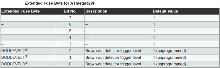
In this table, there are only three usable bits, and the other three are reserved. These three bits deal with the Brownout Detection level. As you can see in the Note if we look at Table 28-5, we can find more details about it.
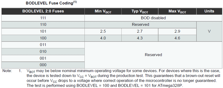
As you can see in the above table, we have the table for Brownout Detection. Brownout detection is a feature that resets the microcontroller when the supply voltage falls below a certain voltage level. In the ATmega328P IC, we can completely disable the brownout detection or we can set it to the levels that are shown in the above table.
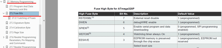
The High Fuse Bytes:
As you can see in the image below, table 27-6: of the datasheet shows the Higher Fuse bits of the ATmega328P IC.
The High fuse deal with various tasks inside the ATmega328 Microcontroller. In this section, we will talk about the Higher fuse bits and their workings. Let’s start with the BOOTRST, BOOTSZ0, and BOOTSZ1 bits. These three bits are responsible for setting the boot size; boot size refers to the amount of memory reserved for installing the bootloader.
A bootloader is a special piece of software that runs on top of the microcontroller and manages different tasks. But in the case of the Arduino, the bootloader is used to upload the Arduino sketch inside the microcontroller. In one of our previous articles, we have shown you How to Burn the Bootloader in ATmega328P Using Arduino. You can check that out if you are interested in the topic. Coming back to our topic, the purposes of other bits in the high byte are made reasonably clear, the EESAVE bit is to preserve the EEPROM memory while under a chip erase cycle is performed. The WDTON bit is to enable or disable the Watchdog Timer.
The watchdog timer is a special timer in the ATmega328P IC which has its separate clock and runs independently. If the watchdog timer is enabled, then you need to clear it with a certain period, otherwise, the watchdog timer will reset the microcontroller. This is a useful feature that comes within many microcontrollers if the processor gets stuck; the watchdog will reset it to prevent any damage to the end application.
The DWEN bit is there to enable the debug wire; this is a preparatory protocol that is internally built into their hardware, that is used to program and debug the processors. With this feature enabled, you can flash and debug the processor with a single wire attached. But to use it, you will need special hardware that is preparatory to Atmel.
The remaining two bits are those bits that you need to avoid unless you exactly know what you are doing. These are the RSTDISBL bit-7 and the SPIEN bit-5. The RSTDISBL (External Reset Disable) as the name implies disables the external hardware reset pin, and the SPIEN bit is used to disable the SPI programming interface. Disabling any of these two bits can completely brick your AVR; so, leaving them alone is a good idea.
The Low Fuse Bytes:
As you can see in the image below, table 27-7: of the datasheet shows the Lower Fuse bits of the ATmega328P IC.
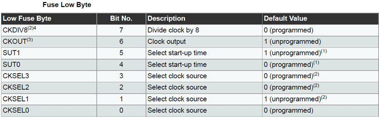
This fuse byte is responsible for setting up the clock source and some other parameters of the clock inside the AVR. In this section, we will learn about all that.
The 7th bit or the CKDIV8 flag can be set to divide the clock source by 8, this comes in very handy which you might already know if you have tried programming the AVR yourself. The next bit is the CKOUT bit and it’s the 6th bit in the Low Fuse Byte. Programming it would output the internal clock signal on the PORTB0 of the microcontroller.
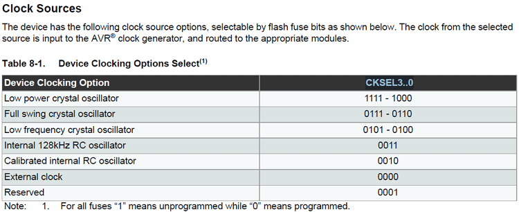
The bits-5 and bit-4 SUT1 and SUT0 control the start-up time of the microcontroller. This prevents any start-up actions which may or may not take place before the supply voltage can reach an acceptable minimum threshold voltage level. And the final four CKSEL0 - 4 bits are used to select the clock source of the microcontroller. The table shown below gives you a better understanding of these four bits which are responsible for setting up the clock source, you can find this table on the Clock Source Section of the datasheet.
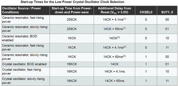
Now, before we get any further, there is one more thing that I should go through is the table for oscillator start-up delay. By start-up delay, we are referring to bits 4 and 5 of the lower fuse byte. The delays need to be set depending upon the condition that the circuit will operate in and the type of oscillator you are using. The default values are set to slow rising power with 6 clock cycles when a power-up or power-down sequence is performed. Next, there is another delay of 14 clock cycles with 65 Ms of delay after start-up.
Phew! That was a lot of information to digest. But before proceeding any further, let’s end this section with a quick note.
Note:
If you have looked at the datasheet carefully, you must have noticed, programming a fuse bit means setting it low, i.e. 0 (zero), which is the opposite of what we generally do to make a port high or low. You have to keep that in mind while configuring your fuses.
Fuse Bits in Arduino
We have talked a lot about fuses in the above section, but in this section, let’s talk about how to configure them and how to write them in a microcontroller. For that, we will need a tool called Avrdude. It is a tool that can be used to read, write, and modify memory in AVR microcontrollers. It works with SPI and it has a long list of support for different types of programmers. you can download the tool from the link given below. Also, we will be using our favorite microcontroller Arduino.
Now, that you have Avrdude, you need to extract that and open a command window in that folder. Also, if you are planning to use it later, you can add the folder path to your windows environment variable section. But I will put it on my desktop and open a command window there. Once we have done that, we will connect the USBasp programmer to our PC and we will make sure that we have the proper driver for our USBasp programmer. Once we do that, we are good to go and we will read the default fuse value first. To do that, you need to run the following command.
avrdude.exe -c usbasp -p m328p -U lfuse:r:low_fuse_val.txt:h -U hfuse:r:high_fuse_val.txt:h -U efuse:r:ext_fuse_val.txt:h
If everything is right, this command will read the fuse bytes and put them into three separate text files. The image below will give you a better idea of the process.
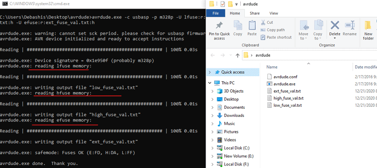
As you can see, the Avrdude read through the fuse bits on the Arduino nano and saved them into three separate text files. Now, we opened them and got three values; for EFUSE: 0xFD, for HFUSE: 0XDA, for LFUSE: 0xFF. This was the default fuse value we got for an Arduino nano. Now, let’s convert these bits to binary and compare them to their default value from the datasheet. The table below shows exactly that.
For convenience, the fuse bits are written in Hexadecimal values, but if we convert them to binary values and compare them to the datasheet, we will know what's happening. Let’s start with the Lower Fuse Byte. As you can see from the above string, it is set to 0XFF and the binary Value would be 0B11111111.
Comparing Stock Lower Fuse Bytes with Arduino:
|
Low Fuse Byte |
Bit No. |
Default Value in AVR |
Default Value of Arduino |
|
CKDIV8 |
7 |
0 (programmed) |
1 (unprogrammed) |
|
CKOUT |
6 |
1 (unprogrammed) |
1 (unprogrammed) |
|
SUT1 |
5 |
1 (unprogrammed) |
1 (unprogrammed) |
|
SUT0 |
4 |
0 (programmed) |
1 (unprogrammed) |
|
CKSEL3 |
3 |
0 (programmed) |
1 (unprogrammed) |
|
CKSEL2 |
2 |
0 (programmed) |
1 (unprogrammed) |
|
CKSEL1 |
1 |
1 (unprogrammed) |
1 (unprogrammed) |
|
CKSEL0 |
0 |
0 (programmed) |
1 (unprogrammed) |
The Higher Fuse Byte is set to 0XDA in binary that is 0B11011010.
Higher Fuse Byte in Binary:
|
High Fuse Byte |
Bit No. |
Default Value in AVR |
Default Value of Arduino |
|
RSTDISBL |
7 |
1 (unprogrammed) |
1 (unprogrammed) |
|
DWEN |
6 |
1 (unprogrammed) |
1 (unprogrammed) |
|
SPIEN |
5 |
0 (programmed) |
0 (programmed) |
|
WDTON |
4 |
1 (unprogrammed) |
1 (unprogrammed) |
|
EESAVE |
3 |
1 (unprogrammed) |
1 (unprogrammed) |
|
BOOTSZ1 |
2 |
0 (programmed) |
0 (programmed) |
|
BOOTSZ0 |
1 |
0 (programmed) |
1 (unprogrammed) |
|
BOOTRST |
0 |
1 (unprogrammed) |
0 (programmed)) |
The Setting for the Extended Fuse Byte is set to 0XFD, in binary it is 0B11111101.
Extended Fuse Byte in Binary:
|
Extended Fuse Byte |
Bit No. |
Default Value in AVR |
Default Value of Arduino |
|
– |
7 |
1 |
1 |
|
– |
6 |
1 |
1 |
|
– |
5 |
1 |
1 |
|
– |
4 |
1 |
1 |
|
– |
3 |
1 |
1 |
|
BODLEVEL2 |
2 |
1 (unprogrammed) |
1 (unprogrammed) |
|
BODLEVEL1 |
1 |
1 (unprogrammed) |
0 (programmed) |
|
BODLEVEL0 |
0 |
1 (unprogrammed) |
1 (unprogrammed) |
Now, this marks the end of this section. As of now, we have learned a lot about the AVR microcontroller and its fuse bits. So, let’s wrap up this article by putting our theory to the test by altering and experimenting with some of the fuse bits in the Arduino Nano.
Components Required to Test Fuses in AVR
We have talked a lot about the fuses in the above part. But to proceed any further in the article, we need some hardware components and some software tools. In this section, we will talk about those. A list of required components with images is shown below.
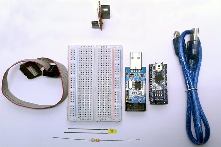
- Breadboard - 1
- Arduino Nano - 1
- USBasp AVR Programmer - 1
- USB Cable - 1
- AVR 10-Pin to 6- Pin Converter - 1
- Avrdude (Software tool for Programming AVR)
- LED - 1
- 330R Resistor - 1
- Jumper Cables
Schematic for Testing the Fuse Bits in AVR
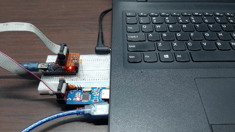
The Hardware testing setup is shown below in this setup. We have connected the Arduino Nano to the PC with a USB cable, and we have also connected the USBasp programmer to the PC. The objective of this article is to program the fuse bits in AVR. For that reason, we have connected the USBasp programmer with the Arduino. The image below will give you a better idea of the setup.

Testing the Fuses in AVR
The testing setup is shown below. As you can see, we have connected the Arduino and the USBasp programmer both to the USB of my laptop.

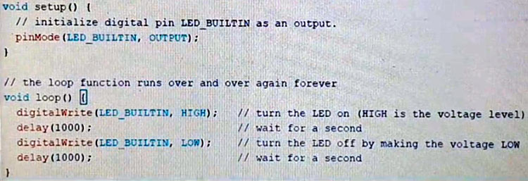
Now let’s open the Arduino IDE and upload a basic blink sketch. The content of the basic blink sketch is self-explanatory, so I did not put any details about it.
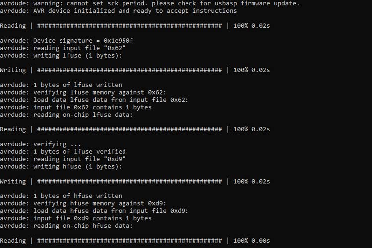
You will see in the video that the led on pin no 13 is blinking as it should. Now let's tweak the fuse settings and set it to its default values. And as we have previously seen in the datasheet; the EFUSE is 0XFF; the HFUSE is D9; The LFUSE is:62. Now let's configure it with Avrdude, flash it, and see what happens. The code we will be using is-
avrdude -c usbasp -p m328P -U lfuse:w:0x62:m -U hfuse:w:0xd9:m -U efuse:w:0xff:m
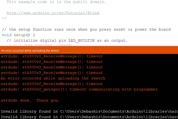
Once I do this, you will see the LED will blink extremely slowly because we have calculated and programmed the value for a 16Mhz clock and now after burning the fuses, it’s only a 1Mhz internal RC oscillator. This is why the LED is blinking so slowly. Now let's try to upload a sketch once again. We will see that the Arduino gives out an error and the code is not uploaded. Because by altering the fuses, we have also messed up the bootloader settings too. You can see that in the below image.
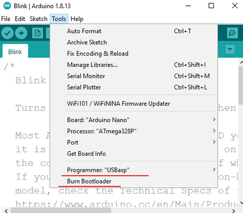
To fix this and to put the Arduino back as it was before, we need to just burn the bootloader again for the Arduino. To do that, go to Tools -> Programmer- USBasp, and once we do that, we can again go to tools and we can click on the burn bootloader option. This will again burn the stock bootloader on your Arduino and everything will go back to as it was before.
After the bootloader was flashed back to the Arduino, it went back to its original state and the last image shows you a blinking LED after the bootloader was burned again.
And this marks the end of this article. I hope you enjoyed the article and learned something new. If you have any questions regarding the article, do not hesitate to put a comment below.

great work