
Arduino is very popular for building hobby projects and games, and we have previously used Arduino to build Snake game, Ping pong game, Space race game, etc. Today we are building one more popular game using Arduino- Buzz wire game or Steady hand game.
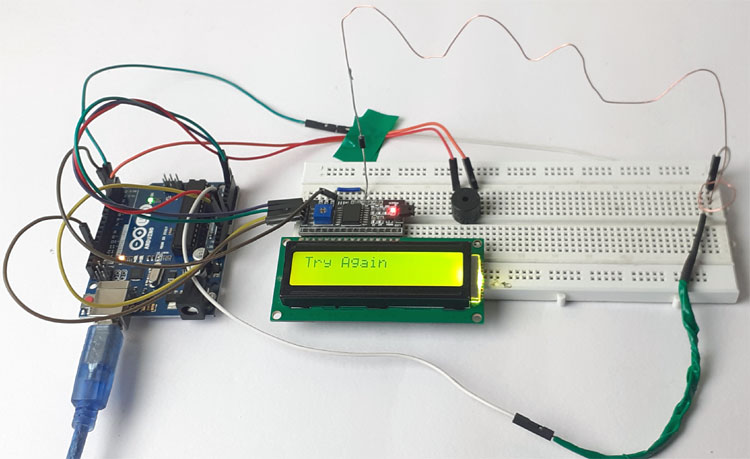
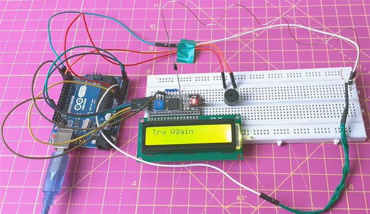
For this project, we will use an Arduino Uno, Buzzer, and two Aluminum wires. A 16x2 LCD is also interfaced to display the game status. Both the ends of the maze wire will be connected to the digital pin 2 & 3 of Arduino, and the handle wire is connected to the Ground pin of Arduino. The digital pins are defined as INPUT_PULLUP pins. So when the handle wire touches the maze wire, it changes the digital pins state to low, and the buzzer makes a sound.
A diode is connected at the end of the maze wire, so when you go past to that diode and touch the maze wire with round handle wire, only one pin (Pin 3) will go low. In that condition, a congratulation text (Well done) will be displayed on LCD.
Components Required
- Arduino Uno
- Aluminium Wire
- 16x2 LCD
- I2C Module
- Breadboard
- Buzzer
- Diode
Circuit Diagram

The circuit diagram for the Arduino Buzz Wire Game is given above. SCL and SDA pins of the I2C module are connected to A5 and A4 pins of Arduino while VCC and GND pin of the I2C module are connected to 5V and GND pin of Arduino. The positive rail of Buzzer is connected to digital pin 4 of Arduino and the negative rail is connected to GND. Cut an aluminum wire and bends it in Zig-Zag shape. Solder a diode at the one end of the wire. Then cut another wire to make a handle and bend one end into a loop.
The 16x2 LCD can also be interfaced with Arduino without using an I2C module.
Connect the D2 & D3 pins of Arduino to both the ends of Zig-Zag wire and connect the handle wire to the GND pin of Arduino.
Code Explanation
Complete code for this Arduino Buzz Wire Game is given at the end of the document.
Start your code by including the library file for the LCD module. LiquidCrystal_I2C.h library is used for I2C communication between Arduino and LCD modules.
#include <LiquidCrystal_I2C.h>
After that, define the Arduino pins for the buzzer, the start point of the wire, and the endpoint of wire.
const int startPin = 2;
const int endPin = 3;
const int buzzer = 4;
Then define two variable start & end_. These variables will be used to save the readings of wire.
int start, end_;
Now define the buzzer pin as output and wire pins as INPUT_PULLUP. Arduino has internal pull-up resistors with a value of around 20k ohm. These resistors can be connected internally using INPUT_PULLUP. Defining an INPUT_PULLUP is functionally the same as connecting a ~20k ohm resistor between the pin and +5V.
pinMode(buzzer, OUTPUT);
pinMode(startPin, INPUT_PULLUP);
pinMode(startPin, INPUT_PULLUP);
Inside the void loop, read the status of the wire pins.
start = digitalRead(startPin);
end_ = digitalRead(endPin);
Now compare the readings of wire pins. If both the pins are low it means, you have touched the wire so buzzer will make a sound, and if the start pin of wire is high and endpin is low that means you reached the endpoint.
if (start == LOW && end_== LOW ){
    digitalWrite(buzzer, HIGH);
    delay(1000);
    digitalWrite(buzzer, LOW);
    lcd.setCursor(0,0);
    lcd.print("Try Again");
    Serial.print("Try Again");
  }
  else if (start == HIGH && end_== LOW){
    lcd.setCursor(0,0);
    lcd.print("Well Done");
    Serial.print("Well Done"); }
Testing the Buzz Wire Game
After connecting the hardware and uploading the given code, you can start playing the game. So hold the wire with a circle in your hand and try to get wire with circle all the way past to the diode soldered with zig-zag wire without letting the round wire touch anywhere. If you touch the wires, then the buzzer will make a sound and LCD will display “Try again”. And if you complete the game without touching the wire, then it will show “Well done”.
This is how you can Make a Buzz Wire Game With an Arduino. A working video and complete code are given below.
Complete Project Code
#include <LiquidCrystal_I2C.h>

LiquidCrystal_I2C lcd(0x27, 16, 2);

const int startPin = 2;

const int endPin = 3;

const int buzzer = 4;

int start, end_;

void setup(void)

{

  Serial.begin(9600);

  lcd.begin();

  lcd.clear();

  pinMode(buzzer, OUTPUT);

  pinMode(startPin, INPUT_PULLUP);

  pinMode(startPin, INPUT_PULLUP);

}

void loop(void)

{

  start = digitalRead(startPin);

  end_ = digitalRead(endPin);

  Serial.print(start);

  Serial.print("\n");

  Serial.print(end_);

  if (start == LOW && end_== LOW ){

    digitalWrite(buzzer, HIGH);

    delay(1000);

    digitalWrite(buzzer, LOW);

    lcd.setCursor(0,0);

    lcd.print("Try Again");

    Serial.print("Try Again");

  }

  else if (start == HIGH && end_== LOW){

    lcd.setCursor(0,0);

    lcd.print("Well Done");

    Serial.print("Well Done");

  }

 delay(500);

}
Comments
Hi! I think you might have a typo here:
pinMode(startPin, INPUT_PULLUP);
pinMode(startPin, INPUT_PULLUP);
Should it be endPin instead?

hello ashish!
this project isn't working!!!