

Relays are common in many switching circuits where controlling (turning ON or OFF) an AC load is required. But due to the electromechanical characteristic, a mechanical relay has a self-life, and also it can only toggle the status of the load and cannot perform other switching operations like dimming or speed control. Apart from this, an electromechanical relay also produces click sounds and high voltage spark when huge inductive loads are turned ON or OFF. You can check out the article on Working of Relays to know more about relays, its construction, and types.
The best alternative for an electromechanical relay is a solid-state relay. A solid-state relay is a type of semiconductor-based relay that can be used as a substitute for an electromechanical relay to control electrical loads. It doesn't have any coils and hence does not need a magnetic field to operate. It also does not have any springs or mechanical contacts hence no wear and tear and can operate on low current. These solid-state relay often recognized as SSR uses semiconductors that control the ON-OFF function of the load as well as can be used to control the speed of motors as well as dimmer. We have also used a solid-state device like TRIAC to control motor speed and to control the Light intensity of an AC load in previous projects.
In this project, we will make a Solid-State Relay using a single component and we will control an AC load in 230VAC operation. The specification used here is limited, we have chosen 2A of Load to be operated using this Solid-State-Relay. The aim is to build a compact PCB for a solid state relay that could be directly interfaced and controlled with the 3.3V GPIO pins of Nodemcu or ESP8266. To accomplish that we have fabricated our PCB boards from PCBWay and we will assemble and test the same in this project. So let's get started !!!
Components Required to Build a Solid-State Relay
- A PCB
- ACST210-8BTR
- 330R resistor ¼ Watt
- Terminal Block (300V 5A)
- 0805 LED with any color
- 150R resistor
Solid State Relay using TRIAC – Circuit Diagram
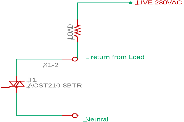
The main component is the ACS Triac or ACST for short. The part number of the ACST is ACST210-8BTR. However, the resistor R1 is used to connect the microcontroller or secondary circuit (control circuit) GND with the AC Neutral. The value of the resistor can be anything in between 390R-470R or can be used more slightly than that also.

For more information about the working of the circuit, it is described in the section below. As mentioned earlier, the main component is the T1, ACST210-8BTR. ACST is a type of TRIAC and is also called triode for alternating current.
How does an ACS TRIAC (ASCT) Work?
Before understanding how an ACST works, it is important to understand how TRIAC works. TRIAC is a three-terminal electronic component that conducts current in either direction when triggered using its gate. Thus it is called a bidirectional triode thyristor. TRIAC has three terminals where "A1" is Anode 1, "A2" is Anode 2, and "G" is Gate. Sometimes, it is also referred to as Anode 1 and Anode 2 or Main Terminal 1 (MT1) and Main Terminal 2 (MT2) respectively. Now, the gate of a TRIAC needs to be provided a small amount of current from the AC source using Opto thyristors, for example, such as MOC3021.
But, the ACST is a bit different from normal TRIAC. ACST is a type of TRIAC from STMicroelectronics but it can be directly interfaced with a microcontroller unit and can be triggered using a small amount of DC without needing an optocoupler. As per the datasheet, the ACST does not require any snubber circuit also for 2A of Inductive Load.
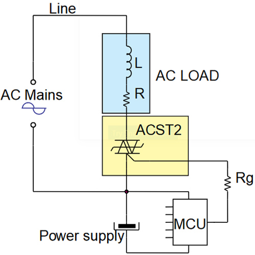
The above circuit is an illustration of the application circuit of ACST. The Line is the LIVE Line of the 230VAC and the Neutral line is connected with the common pin of the ACST. The gate resistor is used to control the output current. However, this resistor can also be used in the Neutral line with the ground or can be eliminated depending on the MCU current output.
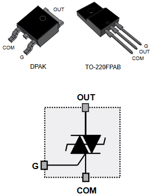
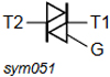
The above image illustrates the pinout of the ACST. One interesting thing is, there is a difference between the pinout with the standard TRIAC and an ACS TRIAC. A standard TRIAC pinout is shown below for comparison, it is a BT136 TRIAC pinout.
As we can see, instead of T1 and T2 (Terminal 1 and Terminal 2), the ACST has Out and Common pins. The common pin needs to be connected with the ground pin of the microcontroller. Thus, it is not acting as bidirectional as the TRIAC. The load should be connected in series with the ACST.
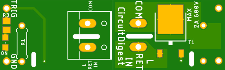
Solid State Relay using TRIAC – PCB Design
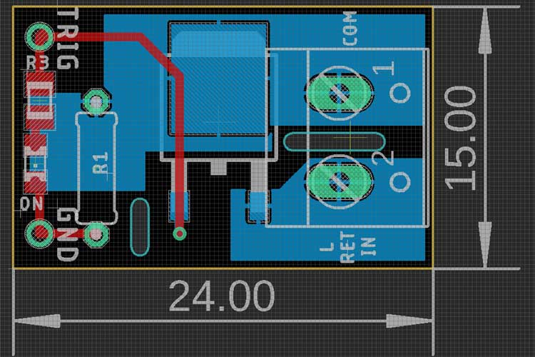
The PCB is designed in 24mm / 15mm size. The adequate heatsink is provided across the ACST using the copper layer. However, the updated Gerber for this PCB is provided in the link below. The Gerber is updated after the testing because there were some design mistakes.
During the test, the same size PCB with the different circuit is used where a provision of MOC3021 is given but it is later removed in the updated Gerber.
The complete PCB design including the Gerber file and schematic can be downloaded from the link below.
Ordering PCB from PCBWay
Now after finalizing the design, you can proceed with ordering the PCB:
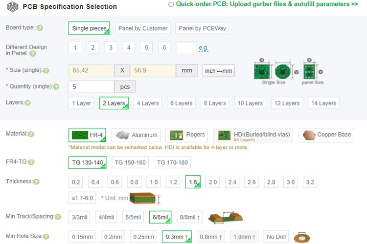
Step 1: Get into https://www.pcbway.com/, sign up if this is your first time. Then, in the PCB Prototype tab, enter the dimensions of your PCB, the number of layers, and the number of PCB you require.

Step 2: Proceed by clicking on the ‘Quote Now’ button. You will be taken to a page where to set a few additional parameters like the Board type, Layers, Material for PCB, Thickness, and more, most of them are selected by default, if you are opting for any specific parameters, you can select it in here.
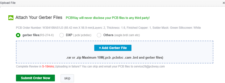
Step 3: The final step is to upload the Gerber file and proceed with the payment. To make sure the process is smooth, PCBWAY verifies if your Gerber file is valid before proceeding with the payment. This way, you can sure that your PCB is fabrication friendly and will reach you as committed.

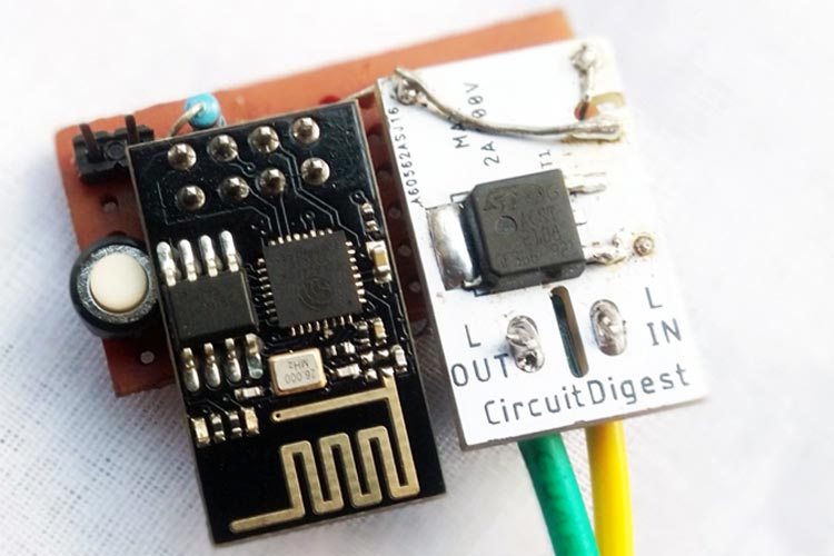
Assembling the Solid-State Relay
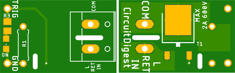
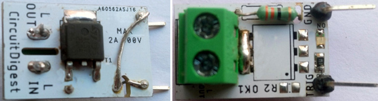
After a few days, we received our PCB in a neat package and the PCB quality was good as always. The top layer and the bottom layer of the board are shown below.
Since this was the first time for me to work with ACST, things did not go as per plan as I told earlier. I had to make some changes. The final circuit after making all the changes are shown below. You need not worry about the changes because they are already made and updated on the Gerber file that you downloaded from the above section.
Programming ESP8266 to control our Solid-State Relay
The code is simple. Two GPIO pins are available in ESP8266-01. GPIO 0 is selected as a button pin and GPIO 2 is selected as the Relay pin. When the button pin is read, if the button is pressed, the relay will change the state ON or OFF or vice versa. However, for trouble-free operation, a debounce delay is also used. You can learn more about switch debouncing in the linked article. Since the code is very simple, we will not be discussing it here. The complete code can be found at the bottom of this page.
Testing our Solid-State Relay
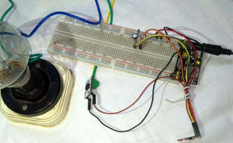
The circuit is connected with the ESP8266-01 with a 3.3V power source. Also, a 100-Watt Bulb is used for testing purposes. As you can see in the above image, I have powered our ESP module with a breadboard power supply module and used two buttons to turn our load on and off.
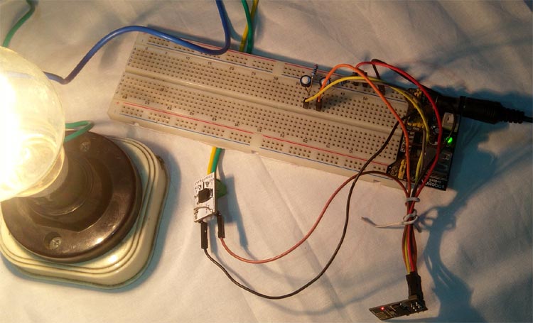
When the button is pressed, the Light is turned ON. Later after testing, I soldered both the solid-state relay and ESP826 module onto a single board to achieve a compact solution as shown below. Now for demonstration purposes, we have used a push button to turn on the load but in the actual application, we will turn it on remotely by writing our program accordingly.
The full explanation and working video can be seen in the link below. Hope you enjoyed the project and learned something useful, if you have any questions, please leave them in the comment section below or use our forums to start a discussion on this.
Complete Project Code
/ constants won't change. They're used here to set pin numbers:
const int buttonPin = 0;       // the number of the pushbutton pin
const int relayPin =  2;        // the number of the LED pin
// variables will change:
int buttonState = LOW;       // variable for reading the pushbutton status
int lastButtonState = LOW;
int ledStateBit=0;
// milliseconds will quickly become a bigger number than can be stored in an int.
unsigned long lastDebounceTime = 0;  // the last time the output pin was toggled
unsigned long debounceDelay = 50;              // the debounce time; increase if the output flickers
void setup() {
  // initialize the LED pin as an output:
  pinMode(relayPin, OUTPUT);
  // initialize the pushbutton pin as an input:
  pinMode(buttonPin, INPUT);
  //pinMode(buttonPin, INPUT_PULLUP);
  //attachInterrupt(digitalPinToInterrupt(buttonPin), buttonISR, CHANGE);
}
void loop() {
  // turn LED on:
  int currButtonState = digitalRead(buttonPin);
  if (currButtonState != lastButtonState) {
                // reset the debouncing timer
                lastDebounceTime = millis();
  }
  if ((millis() - lastDebounceTime) > debounceDelay) {
                // whatever the reading is at, it's been there for longer than the debounce
                // delay, so take it as the actual current state:
                // if the button state has changed:
                if (currButtonState != buttonState) {
                buttonState = currButtonState;
                // only toggle the LED if the new button state is HIGH
                if(buttonState == LOW){
                ledStateBit ^= 1;
                }
                }
  }
  digitalWrite(relayPin, ledStateBit);
  // save the reading. Next time through the loop, it'll be the lastButtonState:
  lastButtonState = currButtonState;
}Comments
I would like to know if this is for UK or USA? In USA we cannot get 230 with one line and a nuetral. Is there something I am missing here? Thanks for your patience
JPF
Bump
Thanks for the info and very well explained. I would love to build one.
Just one question is it OK to use the BT136 in place of the ACST and do we still need to have the Neutral and gnd lines connected? Since, BT136 is easier to get and cheaper too.
Thanks again.

When using normal triac (Q4004L4), do you mean to connect the ground supply of esp8266 to neutral of AC lines? I am scared of doing that I am not sure if it is safe.