
Since the outbreak of Covid-19, infrared thermometers are being used as a screening tool to scan the people at Airports, Railway Stations, and other crowded establishments. These scans are being used to identify potential patients of Covid-19. The government made it compulsory to scan everyone before entering the office, school, or any other crowded place.
So in this tutorial, we are going to build an RFID based Contactless Temperature Monitoring System using a contactless temperature sensor with Arduino. When employees scan the RFID card, it will measure the body temperature of employees with a non-contact infrared thermometer and log the Name and Temperature of that employee directly to the excel sheet. We will be using Arduino Nano, MLX90614, EM18 RFID Reader, and Ultrasonic Sensor to build this project. The ultrasonic sensor is used to calculate the distance between the thermometer and the person. The thermometer will only measure the temperature when the distance is less than 25 CM. It is something like an RFID based attendance system, which also records the body temperature of every person.
Components Required
- Arduino Nano
- EM-18 RFID Module
- MLX90614 Contactless Temperature Sensor
- Ultrasonic Sensor
- Breadboard
- Jumper Wires
EM18 RFID Reader Module
One of the widely used RFID readers for reading 125 kHz tags is the EM-18 RFID Reader. This low-cost RFID Reader module features low power consumption, low form factor, and easy to use. EM-18 Reader Module can provide output through two communication interfaces i.e. RS232 and WEIGAND26.
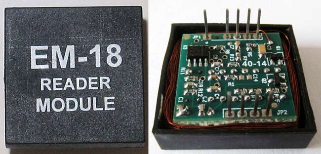

EM18 RFID Reader features a transceiver that transmits a radio signal. When the RFID tag comes in the transmitter signal range, this signal hits the transponder that is inside the card. The tag draws power from the reader module-generated electromagnet field. The transponder then transforms the radio signal into the usable form of power. Upon getting power, the transponder transfers all the information, such as a specific ID, in the form of an RF signal to the RFID Module. Then this data sent to the microcontroller using UART communication.
To learn more about RFID and tags, check our previous RFID based projects.
MLX90614 Infrared Thermometer
Before we proceed with the tutorial, it is important to know how the MLX90614 sensor works. There are many temperature sensors available in the market and we have been using the DHT11 Sensor and LM35 extensively for many applications where atmospheric humidity or temperature has to be measured.
We previously used this sensor in IR thermal gun which can sense the temperature of a particular object (not ambient) without directly getting in contact with the object. Here we are again using the same sensor to calculate the temperature of an object. The MLX90614 is one such sensor that uses IR energy to detect the temperature of an object. To learn more about Infrared and IR sensor circuit, follow the link.
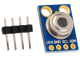
MLX90614 sensor is manufactured by the Melexis Microelectronics Integrated system, it has two devices embedded in it, one is the infrared thermopile detector (sensing unit) and the other is a signal conditioning DSP device (computational unit). It works based on Stefan-Boltzmann law which states that all objects emit IR energy and the intensity of this energy will be directly proportional to the temperature of that object. The sensing unit in the sensor measures how much IR energy is emitted by a targeted object and the computational unit converts it into temperature value using a 17-bit in-built ADC and outputs the data through the I2C communication protocol. The sensor measures both the object temperature and ambient temperature to calibrate the object temperature value. Features of MLX90614 sensor is given below, for more details refer the MLX90614 Datasheet.
Circuit Diagram
Circuit Diagram for RFID based non-contact temperature sensor using Arduino is given below:

As shown in the circuit diagram, the connections are very simple since we have used them as modules, we can directly build them on a breadboard. The LED connected to the BUZ pin of the EM18 Reader module turns high when someone scans the tag. The RFID module sends data to the controller in serial; hence the transmitter pin of the RFID module is connected to the Receiver pin of Arduino. The connections are further classified in the table below:
Arduino Nano | EM18 RFID Module |
5V | Vcc |
GND | GND |
5V | SEL |
Rx | Tx |
Arduino Nano | MLX90614 |
5V | Vcc |
GND | GND |
A5 | SCL |
A4 | SDA |
Arduino Nano | Ultrasonic Sensor (HCSR-04) |
5V | Vcc |
GND | GND |
D5 | Trig |
D6 | Echo |

Code Explanation
We have to write an Arduino code that can read data from the ultrasonic sensor, MLX90614, EM18 RFID Reader Module, and send the Name and Temperature of a person to an Excel Sheet. For this code, you have to download the Wire and MLX90614 libraries. After downloading the libraries, add them to your Arduino IDE.
The complete code for this contactless body temperature monitoring is given at the end of the page. Here the same program will be explained in small snippets.
As usual, start the code by including all the required libraries. Here the Wire library is used to communicate using I2C protocol and the Adafruit_MLX90614.h library is used to read the MLX90614 sensor data.
#include <Wire.h>
#include <Adafruit_MLX90614.h>
We then define the pins of the ultrasonic sensor to which we have made the connection
const int trigPin = 5;
const int echoPin = 6;
After that, define the variables to store the RFID module, ultrasonic sensor, and MLX90614 sensor data.
long duration;
int distance;
String RfidReading;
float TempReading;
Inside the void setup() function, we initialize serial monitor for debugging and the MLX90614 temperature sensor. Also, set the Trig and Echo pins as output and input pins.
void setup()
{
  Serial.begin(9600);   // Initialise Serial Communication with the Serial Monitor
  pinMode(trigPin, OUTPUT);
  pinMode(echoPin, INPUT);
  mlx.begin();
  Initialize_streamer();
}
Inside the void loop() function, calculate the distance between the person and the sensor and if the distance is less than or equal to 25cm, then call the reader() function to scan the tag.
void loop()
{
  digitalWrite(trigPin, LOW);
  delayMicroseconds(2);
  digitalWrite(trigPin, HIGH);
  delayMicroseconds(10);
  digitalWrite(trigPin, LOW);
  duration = pulseIn(echoPin, HIGH);
  distance = duration * 0.0340 / 2;
  if (distance <= 25){
  reader();  }
void reader() function is used to read the RFID tag card. Once the card is brought near the reader module, the reader module reads the serial data and store it in the input variable.
void reader()
{
if(Serial.available())
  {
    count = 0;
    while(Serial.available() && count < 12)
    {
      input[count] = Serial.read();
      count++;
      delay(5);
In the next lines, compare the scanned card data with the predefined tag ID. If the tag ID matches the scanned card, then read the temperature of the person and send the temperature and name of the person to the excel sheet.
if(input[count]==tag[count])
flag = 1;        else
flag= 0;
count++;
RfidReading = "Ashish";
      }
    }
    if(flag == 1)
    {
      temp_read();
      Write_streamer();
      }
Inside the temp_read() function, read the MLX90614 sensor data in Celsius and store it in the ‘TempReading’ variable.
void temp_read()
{
   TempReading = mlx.readObjectTempC();}
Once the hardware and the software are ready, it is time to upload the program into your Arduino Nano Board. As soon your program gets uploaded, the ultrasonic sensor starts calculating the distance. When the calculated distance is less than 40 cm, it reads the temperature and the card.

Storing Sensor Data into Excel Sheet from Arduino Controller
Now to send data to Excel sheet, we are going to use PLX-DAQ. It is an Excel Plug-in software that helps you to write values from Arduino to directly into an Excel sheet on your Laptop or PC. Use the link to download the the file. After downloading extract the file and click on .exe file to install it. It will create a folder named PLS-DAQ on your desktop.
Now open the ‘PLX-DAQ spreadsheet’ file from the desktop folder. If macros are disabled on your Excel than you will see a security block as shown in below image:

Click on Options->Enable the content -> Finish -> OK to Enable the Macros. After this you will get the following screen:

Now select the baud rate as “9600” and the port to which your Arduino is connected and then click on Connect to start the data streaming. Your values should start to get logged like shown in the picture below.

This is how you can build a Contactless Temperature screening device and store the data in the Excel Sheet.
A working video and complete code are given at the end of the page.
Complete Project Code
#include <Wire.h>
#include <Adafruit_MLX90614.h>
Adafruit_MLX90614 mlx = Adafruit_MLX90614();
char tag[] ="180088FECCA2"; // Replace with your own Tag ID
char input[12];        // A variable to store the Tag ID being presented
int count = 0;        // A counter variable to navigate through the input[] character array
boolean flag = 0;     // A variable to store the Tag match status
const int trigPin = 5;
const int echoPin = 6;
long duration;
int distance;
String RfidReading;
float TempReading;
void setup()
{
  Serial.begin(9600);   // Initialise Serial Communication with the Serial Monitor
  pinMode(trigPin, OUTPUT);
  pinMode(echoPin, INPUT);
  mlx.begin();
  Initialize_streamer();
}
void loop()
{
  digitalWrite(trigPin, LOW);
  delayMicroseconds(2);
  digitalWrite(trigPin, HIGH);
  delayMicroseconds(10);
  digitalWrite(trigPin, LOW);
  duration = pulseIn(echoPin, HIGH);
  distance = duration * 0.0340 / 2;
 // Serial.println("Distance");
  //Serial.println(distance);
  if (distance <= 40){
  reader();
  }
  delay(1000);
}
void reader()
{
if(Serial.available())// Check if there is incoming data in the RFID Reader Serial Buffer.
  {
    count = 0; // Reset the counter to zero
    while(Serial.available() && count < 12)
    {
      input[count] = Serial.read(); // Read 1 Byte of data and store it in the input[] variable
      count++; // increment counter
      delay(5);
    }
    if(count == 12) //
    {
      count =0; // reset counter varibale to 0
      flag = 1;
      while(count<12 && flag !=0)
      {
        if(input[count]==tag[count])
        flag = 1; // everytime the values match, we set the flag variable to 1
        else
        flag= 0;
        count++; // increment i
        RfidReading = "Ashish";
      }
    }
    if(flag == 1) // If flag variable is 1, then it means the tags match
    {
      //Serial.println("Access Allowed!");
      temp_read();
      Write_streamer();
      }
    else
    {
     // Serial.println("Access Denied"); // Incorrect Tag Message
    }
    for(count=0; count<12; count++)
    {
      input[count]= 'F';
    }
    count = 0; // Reset counter variable
  }
}
void temp_read()
{
   TempReading = mlx.readObjectTempC();
  // Serial.println(sensorReading1);
  // Serial.print(",");
 //Serial.print("Ambient ");
 //Serial.print(mlx.readAmbientTempC());
 //Serial.print(" C");
// Serial.print("Target  ");
// Serial.print(mlx.readObjectTempC());
// Serial.print(" C");
// delay(1000);
}
void Initialize_streamer()
{
Serial.println("CLEARDATA"); //clears up any data left from previous projects
Serial.println("LABEL,Date,Time,Temperature,Name"); //always write LABEL, to indicate it as first line
}
void Write_streamer()
  {
   // Serial.print("DATA"); //always write "DATA" to Indicate the following as Data
   // Serial.print(","); //Move to next column using a ","
  //  Serial.print("DATE"); //Store date on Excel
   // Serial.print(","); //Move to next column using a ","
   // Serial.print("TIME"); //Store date on Excel
   // Serial.print(","); //Move to next column using a ","
    Serial.print(RfidReading); //Store date on Excel
    Serial.print(","); //Move to next column using a ","
    Serial.print(TempReading); //Store date on Excel
    Serial.print(","); //Move to next column using a ","
    Serial.println(); //End of Row move to next row
}Comments
Hallo,
ein sehr schönes Projekt, das ich gerne umsetzen möchte.
Leider habe ich folgendes Problem:
Beim Lesen der Card-ID in meinem RFID-Reader erhalte ich bei meinen Karten nur eine 11-stellige ID zum Beispiel 8009C7A25EB und am Ende ein anderes unlesbares 12. Zeichen.
Was mache ich falsch?
Wenn ich diese ID dann in ihrem Projekt nutze, funktioniert zwar der Ultrasonic Sensor (HCSR-04) und berechnet die richtige Distance aber der Reader liest keine ID ein und das Screening funktioniert nicht.
Können sie mir helfen?
Vielen Dank
Hello
for learning purposes i have try to build this project and i got a problem with the PLX-DAQ which i cant transfer the data that EM-18 read to excel, is there any solution for this ? I would like to know it
I have test the reading output in serial monitor and its working
Thank you
What problem? Can you elaborate
I have followed the steps just like at the video and successfully connect plx-daq to arduino but the problem is when i scan my rfid card to em-18, the read output data won't show at my excel so the table consist of date,name and temperature is just empty even though i scan the card
Have you selected the right COM port on PLX-DAQ. Perhaps sharing a screen shot might help
Yes, i have selected the right COM port
Anyway i have found my solution for the output
Thank you for all the replies you all been give
Hello,
Can we add a Led for evey successful scan and where to place it ?
I have one more doubt i have an rfid card how do i register this card to be read by the rfid reader?
Hi Henry, you can add another Card number as tag2[] ="" and then compare it with the input in while loop same as first card. AND yes you can blink an led for successsful scan. for example
if(input[count]==tag[count]){
digitalWrite(LED,HIGH);
delay(1000);
digitalWrite(LED,LOW);
}
char tag[] ="180088FECCA2"; // Replace with your own Tag ID
Here, the number is the one that is printed on rfid tag?
I have an tag whose printed number on tag is
0010479458 159, 59234 so what is my equivalent number to be entered because its clearly more than 12 digits?
Please help and give the number for my tag
There is an arduino code to find the tag number. Follow the link https://circuitdigest.com/microcontroller-projects/fingerprint-based-ca….
I think there is a mistake in code at line 97
There are four columns created while in video u posted has 3 in different format
Also how do you print the current date? In video you print date name and temperature .
Please check it and send modified code on tejas.raut1412@gmail.com email id
I tried the running the program today and in plxdaq it created the columns but when i scanned no data was filled so i checked the code and got the mistake as mentioned above
Please please send the correct code
Thanks for replies
Last request just delete my previous comment as it contains an email id
I can't delete it from here
Please delete it
URGENT
Can I please have a clear picture of the circuit from above? I'm a beginner and confused with the wiring diagram.
Can i change arduino nano to arduino uno? If can, do i need to change anything?
Data does not upload to the excel sheet. How do I fix?
Good day sir, is there an alternative component for the EM18 RFID reader module? And if there's any, may I ask for help with the pin configuration connection? Hopping for your response, ThankYou.
Good day Sir Ashish Choudhary, I would like to ask if there is an alternative component for the EM18 RFID reader module? Is RC522 RFID Module okay? If it is, may I ask for your help with the pin configuration connection?
Yeah you can use RC522 in place of EM-18. Follow the link for mor information on how to interface RC522 with Arduino:
https://circuitdigest.com/microcontroller-projects/login-to-windows-com…
Hello Ashish. i am a student trying the project you have done. the thing is if i was using RC522, is the coding need to be change because when i have done the same step as you, the program didn't operate at all.
You cannot same code for RC522. you need to do some changes in code. you should use RC522 library in your code.
Hello sir, can i know what happen when someone tag the rfid and got the high temperature.It is just shows in the excel sheet ?
Can we add the buzzer for shows the output when the high temperature and where to place it?
Yes ! you can add buzzer or LED in arduino , for this you have to apply some conditions in code. you can set any limit of tempereature, buzzer will sound when the limit is exceeded.
Hello sir, can you suggest the virtual simulator for mlx90614
Simulator for mlx90614 is not availabe as of now but if you just want to test your circuit then you can use any IR sensor in proteus.
Hello sir,
I would like to build this setup. could you please suggest, where can I get all the components?
If you want to do it in simulation then you can use EasyEDA software.
if you want to do in hardware then you can get all these component from Quartz component. i am sharing the link of quartz component here
Thank you for the information.
I am trying to make the setup at UHF frequency. could you share your mail id for further discussion or could you please accept my friend request in linkedin platform.
Hi sir, could you please clarify - whether the same code works for Arduino Mega 2560
Hello sir, I am working on this as a project for one of my courses. I have done everything as shown in the page but I am unable to view any output. Kindly clarify. I have attached the serial monitor screen image.

Hello,
I have done some minimal searching for the individual items required for this project and some seem rather pricey. What is the ebest way to get info. on the availaibilty and general pricing on these components?
Thank you.