
If you are an electronics hobbyist then you must have heard about the 555 timer IC and its 3 popular circuits viz. astable multivibrator, bistable multivibrator, and monostable multivibrator. Apart from these, there are other popular circuits like 555 timer IC as a switch and police hooter that we have talked about previously. Adding to the list, there is also one more type of siren circuit that we can design using this IC. We are talking about the wailing siren circuit which produces a tone, the intensity of which is dependent on the time till the button is pressed. We can use this circuit in designing security systems.
In this project, we will use astable mode of the IC with some external components to make the wailing siren. For demonstration, I designed the circuit on the breadboard.
Components Required for Building Wailing Siren Circuit
The components needed for designing a wailing siren circuit on the breadboard are given below:
- Breadboard
- 555-timer IC
- Resistors: 22k, 100k, 33k, 220k*2
- Capacitors: 100uf, 10nf
- Transistors: BC547 and BC557
- 9V battery
- 8-ohm speaker
Introduction to the 555 Timer IC
When it comes to designing timer circuits, the very first thing which comes to mind is the 555 timer IC. It’s the oldest piece of tech and thus you can rely on it blindly and best of all, it’s affordable. The internal circuit of the 555-timer is given below.
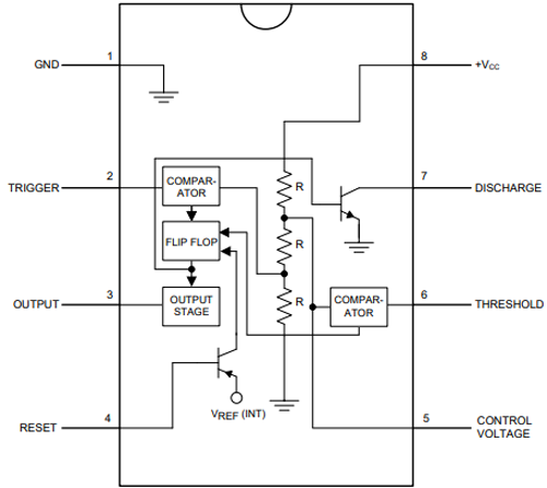
- PIN 1 and PIN 8: These are connected between the ground and Vcc with three 5kΩ resistors. This also gives the IC it’s iconic name. These resistors create a voltage divider circuit with the value of 1/3 and 2/3 of the supply voltage as pin 1 is ground and pin 8 is Vcc. The non-inverting input(+) of one comparator is connected to the 1/3 output of the voltage divider and the inverting input(-) of the other comparator is connected to the 2/3 output of the voltage divider.
- PIN 2: It is the trigger pin of the IC which is connected to the inverting input(-) of the comparator.
- PIN 3: It is the output of the IC which is connected via the output driver circuit to the output of a flip-flop.
- PIN 4: It is the reset pin that is connected to the reset pin of the flip-flop. By connecting this pin to the ground, we can reset this IC. This is the reason we see in most 555 circuits, it is connected to Vcc.
- PIN 5: It is the control pin that is connected to the 2/3 value of the voltage divider and inverting input(-) of the comparator. If we want to change the reference voltage, we can apply external voltage via this pin. Generally, in most of the 555 timer circuits, we can see that this pin is connected to a capacitor for getting a stable reference voltage.
- PIN 6: It is connected to the non-inverting(+) input of the comparator circuit whose output is connected to the reset pin of the flip-flop.
- PIN 7: It is the discharge pin that is connected to the collector of the BJT.
Circuit Diagram of Wailing Siren Circuit
The circuit diagram of the wailing siren circuit is given below.

In this circuit, we are using the 555-timer IC in astable mode. Similar to most 555 timer circuits the IC pins 2 and 6 are connected and pin 4 is connected to the ground. A PNP transistor is connected as a switch between the supply voltage and pin 8 of the IC. The base of this transistor is connected to the 100uf capacitor through a 100K resistor. The output pin 3 of the IC is connected to the base of an NPN transistor. This transistor works as a switch for driving the 8-ohm output speaker.
Working of the Siren Circuit
From the circuit, we can see that the IC is powered through a PNP transistor. Since it is a PNP transistor, it means the negative voltage at the gate will turn it on. Initially, when the supply is turned on, the capacitor starts to charge through the 100k and 220k resistor, and due to this fully charged capacitor, there is a positive voltage at the gate of the transistor which switches it off. When we press the push button the capacitor finds a way to discharge through the 22k resistor which in result provides a negative voltage at the transistor that turns it on.
This phenomenon creates a wailing siren because the charging and discharging of the capacitor takes time. This is the reason why the amplitude of the siren changes depending on the time of the button pressed.
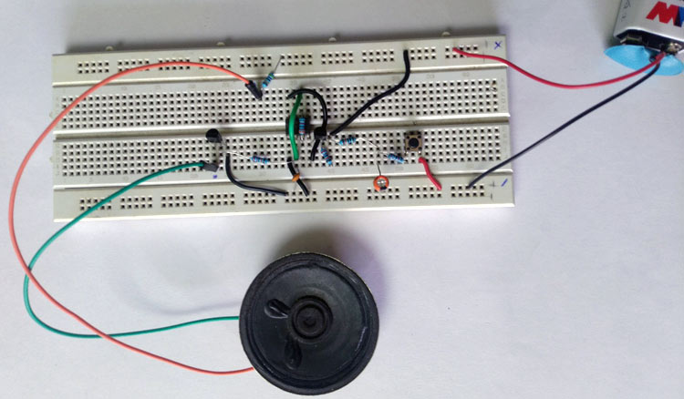
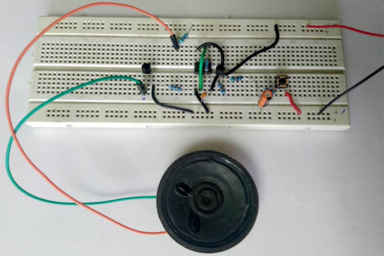
Testing of the Siren Circuit
The images of the designed circuit are given below.
That's all about building a 555-timer based waling siren circuit. The video showing the working of the circuit is given at the end of the article. I hope you understood everything about the concept but still if you have any doubt, feel free to leave a comment below.

Please note pin 4 and 8 are directly connected to B+ In the description it says pin 4 is connected to ground, which it is not. If 4 and 8 are directly connected to B+ how can PNP transistor act as a switch? Does wailing occur when switch is kept pressed? My finished project gave a constant hum at 80 to 100 Hz. The switch had no effect. Please help. Thanks.