
If you are a hobbyist or have keen interest in electronics circuits, you must be familiar with 555 timer IC and its three popular circuits - Monostable multivibrator, Astable multivibrator, and Bistable multivibrator. Guess what, we can even use this IC as a switch. This is the type of button that holds its state i.e. on the first press, it switches on the load, and on the second press, it switches off the load. We can use this circuit in combination with digital development boards like Arduino for designing circuits where we need to activate the microcontroller by detecting a small pulse (like a motion sensor).
In this tutorial, we will learn how we can use a 555 timer IC as a switch in combination with some complementary components. We will design the circuit on a breadboard and with the help of a push-button, we will demonstrate its working.
Components Required for 555 Timer Latch Circuit
The components required to build a simple push on push off switch are listed below.
- 555 timer IC
- 220KΩ resistors * 2
- 100kΩ resistor
- 1KΩ resistor
- 1uF electrolytic capacitor
- LED with 220-ohm resistor
- SPDT Relay
- In4007 diode
- BC557 PNP transistor
Introduction to the 555 Timer IC
When it comes to designing timer circuits, the very first thing which comes in our mind is the 555 timer IC. It’s the oldest piece of technology and thus you can rely on it blindly and best of all, it’s affordable. The internal circuit of the 555-timer is discussed below:
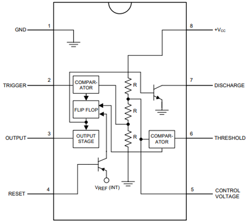
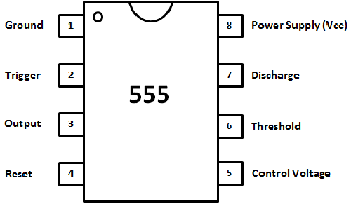
PIN 1 and PIN 8: These are connected between the ground and Vcc with three 5kΩ resistors. This also gives the IC its iconic name. These resistors create a voltage divider circuit with the value of 1/3 and 2/3 of the supply voltage as pin 1 is ground and pin 8 is Vcc. The non-inverting input(+) of one comparator is connected to the 1/3 output of the voltage divider and the inverting input(-) of the other comparator is connected to the 2/3 output of the voltage divider.
PIN 2: It is the trigger pin of the IC which is connected to the inverting input(-) of the comparator.
PIN 3: It is the output of the IC which is connected via the output driver circuit to the output of a flip-flop.
PIN 4: It is the reset pin that is connected to the reset pin of the flip-flop. By connecting this pin to the ground, we can reset this IC. This is the reason, we see in most 555 circuits it is connected to Vcc.
PIN 5: It is the control pin that is connected to the 2/3 value of the voltage divider and inverting input(-) of the comparator. If we want to change the reference voltage, we can apply external voltage via this pin. Generally, in most of the 555 timer circuits, we can see that this pin is connected to a capacitor for getting a stable reference voltage.
PIN 6: It is connected to the non-inverting (+) input of the comparator circuit whose output is connected to the reset pin of the flip-flop.
PIN 7: It is the discharge pin that is connected to the collector of the BJT.
How does a 555-Timer Latching Switch Work?
PIN 2 and 6 of 555-timer are the triggers and threshold pins respectively. In this circuit, we will monitor the voltage at these pins. When the voltage at pin 2 goes below 1/3 of the supply voltage, this pin turns ON the output (pin 3) and when the voltage at pin 6 goes below 2/3 of the supply voltage, this pin turns OFF the output (pin 3).
Circuit Diagram of the 555-Timer latch Circuit
The schematic of the 555-timer based on-off switch is given below.

In the circuit, pin 2 and pin 6 are connected, and pins 4 and 8 are also connected. The output of the voltage divider circuit is connected to pin 6 of the IC. One resistor of the voltage divider circuit is connected via a 1uF capacitor to the output pin 3 through the 100k resistor. A push-button is connected between pin 2 and the capacitor’s positive terminal. An LED is also connected through its current limiting resistor at the output of the IC.
Working of the Push-on Push-off Switch Circuit
Two 220KΩ resistors create a voltage divider circuit. The output of this voltage divider circuit is fed into pin 6 of the IC. When we initially turn ON the circuit, the voltage divider is in the balanced condition so the output is OFF. When we press the push button, the capacitor starts to charge through the resistor R3 and thus the R3 draws more current which creates an unbalanced condition. This creates the change in voltage at pin 2 which in result turns ON the output. Now when we press the button again, pin 6 detects the supply voltage of the charged capacitor. This results in switching OFF the output.
Testing our 555-Timer Latch Circuit
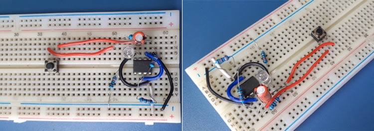
I created the circuit on the breadboard, the video of which is available at the end of the article. Also, the pictures related to the circuit are given below.
NOTE: This is a digital circuit and thus it works on logic levels. Always check the value of the resistors used in the voltage divider as it may differ depending on the tolerance of the resistors and if possible, use high precision resistors. Apart from this, you can use a 0.1uF ceramic capacitor in parallel with the switch if there is any issue in the operation of the circuit.
This is how you can use the 555-timer IC as a switch. If you have any doubts related to the circuit, you can post them in the comment section below.

Schematic has an error. The potential divider should be connected to ground and so should the negative terminal of the capacitor.