

Ever since I started to work with the ESP Wi-Fi Modules, I always wanted to build a smart Wi-Fi socket that enables me to control my AC loads wirelessly through smart phone. While products like these are already available in the market, like the popular Moko WiFi Smart Plug or Sonoff, they are a bit expensive and on top of that it doesn’t give you the joy of building your own. So, in this project I will show you how you can build your very own Smart plug using ESP8266 Wi-Fi module. The device that we built can easily be plugged into any exiting AC socket and then on the other end you can connect the actual load simply by plugging it into this socket on our device. After that just keep the main switch of your socket always on, and you can control your Load directly from your Smartphone. Fun right? So let’s get into the project ….
ESP Smart Plug for Home Automation
We have already built a handful of home automation projects, from simple RF based Home automation to my favorite Google assistant based Voice controlled home automation. But today, the requirement of this project is slightly different.
Here, the purpose is to turn on/off my Wi-Fi router by just using the Smartphone directly from my workstation. Because at times my internet connection goes down and when I call my customer care, the standard answer that I get is “Sir, I am sorry for the inconvenience caused. Please restart your router, by turning it off and then turning it on again after few seconds” Puffff! Tired of walking my way to the router every time, I decided to build this wifi smart plug and control my router using it.
But, wait a minute! I will no longer have access to internet once I turn off my router. So how will I turn it on back again remotely? Luckily, our ESP8266 can be used as an access point, meaning it can also act like a router by sending its own wi-fi signal. This Wi-Fi signal will always be available as long as the ESP8266 is powered. Hence we will program our ESP8266 as a captive portal, that way once we have connected to the ESP’s Wi-Fi signal we will be taken to a webpage from where we can turn on/off our load.
Materials Required
1. ESP8266 Wi-Fi module
2. Hi-Link AC to DC Converter (3.3V)
3. 3V Relay
4. NPN Transistor BC547
5. FTDI Programmer module
7. Connecting wires
Note: We are using this Arduino Wi-Fi Shield that we build earlier. The board is only used to upload the Arduino code into the ESP8266 module. If you do not have this board you can either build one using the link of use this simple ESP8266 Programmer circuit to upload your code.
IoT Smart Plug Code for ESP8266
Before we proceed any further let’s dive straight into the program to understand how our DIY WiFi smart plug will work. As you can see here we begin the program by including few header files and setting up a DNS network server
#include <ESP8266WiFi.h>
#include "./DNSServer.h"
#include <ESP8266WebServer.h>

const byte        DNS_PORT = 53;          // 53 is set as DNS port
IPAddress         apIP(10, 10, 10, 1);    // Network Server
DNSServer         dnsServer;              // DNS server object
ESP8266WebServer  webServer(80);          // Webserver object
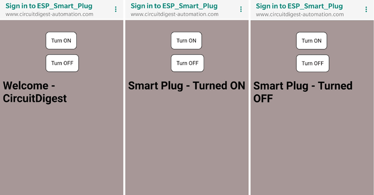
Then we initialize the GPIO pin 2 of ESP as output which will be used to control our load. After which we have a long HTML code for our webpage. Here we totally have three screens on our webpage namely the Home screen, On screen and Off screen.
String Home_Screen = "" //Page 1 - Home Screen HTML code
                      "<!DOCTYPE html><html>"
                      "<head><meta name=\"viewport\" content=\"width=device-width, initial-scale=1\">"
                      + style_detials +
                      "<div id=\"buttons\">"
                      "<a style=\"text-decoration:none;\" href=\"relay_ON\"> <button id=\"switchLight1\" class=\"controllButtons\">Turn ON</button> </a>"
                      "<a style=\"text-decoration:none;\" href=\"relay_OFF\"><button id=\"switchLight2\" class=\"controllButtons\">Turn OFF</button>  </a>"
                      "</div>"
                      "<body><h1>Welcome - CircuitDigest</h1>"
                      "</body></html>";

String ON_Screen = "" //Page 2 - If device is turned ON
                      "<!DOCTYPE html><html>"
                      "<head><meta name=\"viewport\" content=\"width=device-width, initial-scale=1\">"
                      + style_detials +
                      "<div id=\"buttons\">"
                      "<a style=\"text-decoration:none;\" href=\"relay_ON\"> <button id=\"switchLight1\" class=\"controllButtons\">Turn ON</button> </a>"
                      "<a style=\"text-decoration:none;\" href=\"relay_OFF\"><button id=\"switchLight2\" class=\"controllButtons\">Turn OFF</button>  </a>"
                      "</div>"
                      "<body><h1>Smart Plug - Turned ON</h1>"
                      "</body></html>";

String OFF_Screen = "" //Page 3 - If device is turned OFF
                      "<!DOCTYPE html><html>"
                      "<head><meta name=\"viewport\" content=\"width=device-width, initial-scale=1\">"
                      + style_detials +
                      "<div id=\"buttons\">"
                      "<a style=\"text-decoration:none;\" href=\"relay_ON\"> <button id=\"switchLight1\" class=\"controllButtons\">Turn ON</button> </a>"
                      "<a style=\"text-decoration:none;\" href=\"relay_OFF\"><button id=\"switchLight2\" class=\"controllButtons\">Turn OFF</button>  </a>"
                      "</div>"
                      "<body><h1>Smart Plug - Turned OFF</h1>"
                      "</body></html>";
These three WebPages when opened will appear something like this. You can customize your webpage to appear the way you like it.
Then we have our void setup function inside which we define our ESP to work as an Access point and also provide a name for it, here “ESP_Smart_Plug”. When any user gets connected to this Wi-Fi they will be taken to the home page that we defined earlier.
  pinMode(LED_BUILTIN, OUTPUT); //LED pin as output for indication
  pinMode(GPIO_2, OUTPUT); //GPIO pin as output for Relay control

  WiFi.mode(WIFI_AP); //Set ESP in AP mode
  WiFi.softAPConfig(apIP, apIP, IPAddress(255, 255, 255, 0));
  WiFi.softAP("ESP_Smart_Plug"); // Name your AP network

  dnsServer.start(DNS_PORT, "*", apIP);

  webServer.onNotFound([]() {
    webServer.sendHeader("Location", String("http://www.circuitdigest-automation.com/home.html"), true); //Open Home screen by default
    webServer.send ( 302, "text/plain", "");
  });
On the home page if the user clicks on the ON button, the on screen page will be displayed and the GPIO 2 pin will be set high
//ON_Screen
  webServer.on("/relay_ON", [](){ //If turn on Button is pressed
       digitalWrite(LED_BUILTIN, LOW); //Turn off LED
       digitalWrite(GPIO_2, HIGH);  //Turn off Relay
       webServer.send(200, "text/html", ON_Screen); //Display this screen
  });
Similarly if the user clicks on the off button, the off screen page will be displayed and the GPIO 2 pin will be set LOW.
//OF_Screen
  webServer.on("/relay_OFF", [](){ //If turn off Button is pressed
       digitalWrite(LED_BUILTIN, HIGH); //Turn on LED
       digitalWrite(GPIO_2, LOW); //Turn on Relay
       webServer.send(200, "text/html", OFF_Screen); //Display this screen
  });
The complete code along with the library files can be downloaded as a ZIP file from the link given below. Now that our code is ready, we can upload it to our ESP module by simply clicking on the upload button and then wait for the code to be uploaded. The complete program along with the library files can be downloaded from below link
ESP8266 Smart Plug – Arduino Code Download
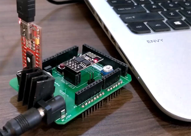
Those who have the Wi-Fi shield can simply plug in your modules together as shown above and connect it to your computer to begin programming our ESP8266 using the Arduino IDE. People who do not have this board can use the circuit diagram as mentioned earlier.
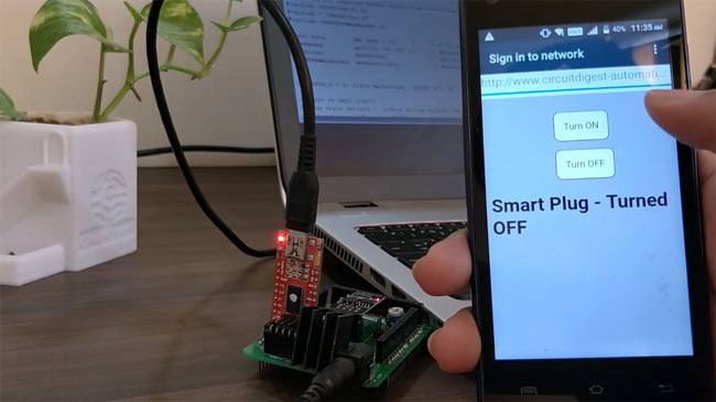
Once the code is uploaded, search for Wi-Fi networks on your phone and you should find a signal named “ESP_Smart_Plug”. Connect to it and you will be taken to the webpage that we just designed. Here when you press the turn off button you should notice the LED on our ESP board turning off and when you press the turn on button the LED should turn on again.
After verifying the code few more times, we will no longer need the programmer board for this project. Now, we have to build a circuit to power our ESP module directly from mains voltage and use its GPIO pin to toggle a relay. To build this circuit I used an AC-DC converter module from Hi-Link which converts the AC mains voltage to 3.3V DC with an output current of 900mA sufficient enough to power up the ESP module through mains. The output side Relay is a 3.3V relay which can be controlled by the GPIO pin of ESP through a transistor like this BC547. We will also need a 1k Resistor to limit the base current of our transistor.
IoT Smart Plug Circuit Diagram
The complete circuit diagram for Wi-Fi smart plug would look like this.

The AC mains to power our project will be obtained through this plug. The other components are the ones that explained eariler. Another important thing to concentrate is on keeping the GPIO-0 and GPIO-2 high while booting up. Else the ESP module will enter programming mode and out code will not work. Hence I have used a 10k (values between 3.3k to 10k can be used) resistor to pull the GPIO pin high by default. Alternatively you can also use a PNP transistor in place of BC547 and switching the relay from high side. With circuit diagram ready, I planned on how to solder these components by keeping the board size as small as possible so that it fits inside a small casing and procedded with soldering the board.
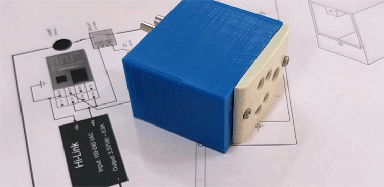
3D Printed Casing for Smart Plug Socket
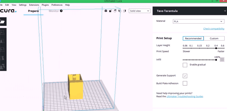
Next I measured the dimensions of the board using my vernier and also measured the dimensions of the plug and socket to design a casing for my smart plug. My design looked something like this below once it was done.

After I was satisfied with the design I exported it as an STL file, sliced it based on printer settings and finally printed it. Again the STL file is also available for download from thingiverse and you can print your own casing using it.
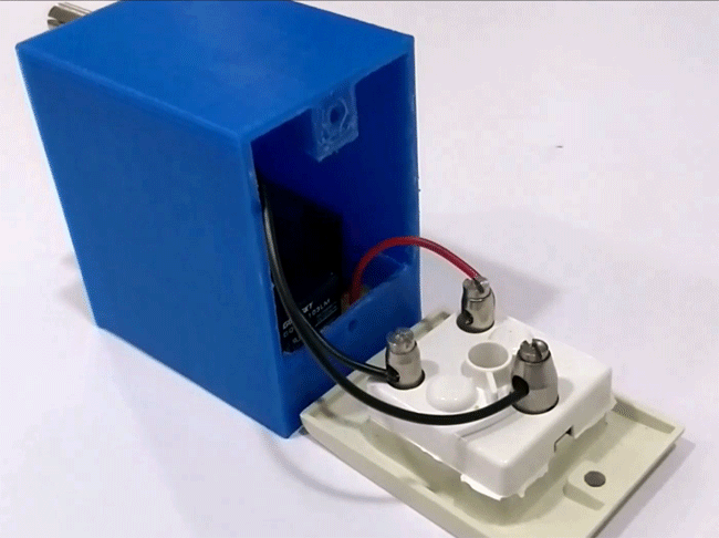
After the print was done I was quite satisfied with the result. Then I proceeded with adding the wires to my board and also screwed them to the power terminals and socket. With the complete connection made I assembled the circuit into my casing and everything was a nice fit as you can see here.
With my smart plug ready for action, I went to my router, traced its wire to find its adapter. Then I removed it from the socket and connected the smart plug to the same socket and turned it on. Now I plugged the adapter back to our smart plug and like that I can hereafter control it from my phone.In the same way you can control any low power AC load in your home and have fun.
Complete code can be downloaded from here and working video for this DIY smart power socket can be found at the bottom of this page. Hope you enjoyed the project, let me know in the comment section what you would automate with this device. If you have any questions leave them in the forum and I will try my best in answering them.
Complete Project Code
/*Smart Plug - Captive Portal Home Automation

 * Requires no Wi-Fi to operate

 * Date:19-8-2019

 * Author: B.Aswinth Raj

 * Website: Circuitdigest.com

 */
//Download all required header filers from circuitdigest.com

#include <ESP8266WiFi.h>

#include "./DNSServer.h"

#include <ESP8266WebServer.h>
const byte        DNS_PORT = 53;          // 53 is set as DNS port

IPAddress         apIP(10, 10, 10, 1);    // Network Server

DNSServer         dnsServer;              // DNS server object

ESP8266WebServer  webServer(80);          // Webserver object

int GPIO_2 = 2; //Pin defanition - Relay will be connected to GPIO-0
/*START OF HMTL CODE*/

String style_detials =  //This String defines the style attributes for webpage

   "<style type=\"text/css\">"

   " body{"

    "  background-color: #a69695;"

    "}"

    "button{"

     " display: inline-block;"

    "}"

    "#buttons{"

     " text-align: center;"

    "}"
    ".controllButtons{"

     " margin-top: 15px;"

      "margin-left: 5px;"

      "background-color: white;"

      "padding: 10px;"

      "border:1px solid black;"

      "border-radius: 10px;"

      "cursor: pointer;"

      "font-size: 14px;"

    "}"
    ".controllButtons:hover{"

     " background-color: orange;"

      "padding: 10px;"

      "border:1px solid black;"

      "border-radius: 10px;"

      "cursor: pointer;"

      "font-size: 14px;"

    "}"
    "@media only screen and (max-width: 700px) {"

     " button{"

      "  display: block;"

      "}"

      "#buttons{"

       " margin-top: 10%;"

        "margin-left: 35%;"

      "}"

       " .controllButtons{"

        "  margin-top: 15px;"

        "margin-left: 5px;"

        "background-color: white;"

        "padding: 15px;"

        "border:1px solid black;"

        "border-radius: 10px;"

        "cursor: pointer;"

        "font-size: 16px;"

      "}"
      ".controllButtons:hover{"

       " background-color: orange;"

        "padding: 15px;"

        "border:1px solid black;"

        "border-radius: 10px;"

        "cursor: pointer;"

        "font-size: 16px;"

      "}"

    "}"
  "</style>";
String Home_Screen = "" //Page 1 - Home Screen HTML code

                      "<!DOCTYPE html><html>"

                      "<head><meta name=\"viewport\" content=\"width=device-width, initial-scale=1\">"

                      + style_detials +

                      "<div id=\"buttons\">"

                      "<a style=\"text-decoration:none;\" href=\"relay_ON\"> <button id=\"switchLight1\" class=\"controllButtons\">Turn ON</button> </a>"

                      "<a style=\"text-decoration:none;\" href=\"relay_OFF\"><button id=\"switchLight2\" class=\"controllButtons\">Turn OFF</button>  </a>"

                      "</div>"

                      "<body><h1>Welcome - CircuitDigest</h1>"

                      "</body></html>";
String ON_Screen = "" //Page 2 - If device is turned ON

                      "<!DOCTYPE html><html>"

                      "<head><meta name=\"viewport\" content=\"width=device-width, initial-scale=1\">"

                      + style_detials +

                      "<div id=\"buttons\">"

                      "<a style=\"text-decoration:none;\" href=\"relay_ON\"> <button id=\"switchLight1\" class=\"controllButtons\">Turn ON</button> </a>"

                      "<a style=\"text-decoration:none;\" href=\"relay_OFF\"><button id=\"switchLight2\" class=\"controllButtons\">Turn OFF</button>  </a>"

                      "</div>"

                      "<body><h1>Smart Plug - Turned ON</h1>"

                      "</body></html>";
String OFF_Screen = "" //Page 3 - If device is turned OFF

                      "<!DOCTYPE html><html>"

                      "<head><meta name=\"viewport\" content=\"width=device-width, initial-scale=1\">"

                      + style_detials +

                      "<div id=\"buttons\">"

                      "<a style=\"text-decoration:none;\" href=\"relay_ON\"> <button id=\"switchLight1\" class=\"controllButtons\">Turn ON</button> </a>"

                      "<a style=\"text-decoration:none;\" href=\"relay_OFF\"><button id=\"switchLight2\" class=\"controllButtons\">Turn OFF</button>  </a>"

                      "</div>"

                      "<body><h1>Smart Plug - Turned OFF</h1>"

                      "</body></html>";


/*END OF HMTL CODE*/


void setup() {

  pinMode(LED_BUILTIN, OUTPUT); //LED pin as output for indication

  pinMode(GPIO_2, OUTPUT); //GPIO pin as output for Relay control


  WiFi.mode(WIFI_AP); //Set ESP in AP mode

  WiFi.softAPConfig(apIP, apIP, IPAddress(255, 255, 255, 0));

  WiFi.softAP("ESP_Smart_Plug"); // Name your AP network
  dnsServer.start(DNS_PORT, "*", apIP);
  webServer.onNotFound([]() {

    webServer.sendHeader("Location", String("http://www.circuitdigest-automation.com/home.html"), true); //Open Home screen by default

    webServer.send ( 302, "text/plain", "");

  });


  webServer.on("/home.html", []() {

    webServer.send(200, "text/html", Home_Screen);

  });

//ON_Screen

  webServer.on("/relay_ON", [](){ //If turn on Button is pressed

       digitalWrite(LED_BUILTIN, LOW); //Turn off LED

       digitalWrite(GPIO_2, HIGH);  //Turn off Relay

       webServer.send(200, "text/html", ON_Screen); //Display this screen

  });

//OFF_Screen

  webServer.on("/relay_OFF", [](){ //If turn off Button is pressed

       digitalWrite(LED_BUILTIN, HIGH); //Turn on LED

       digitalWrite(GPIO_2, LOW); //Turn on Relay

       webServer.send(200, "text/html", OFF_Screen); //Display this screen

  });


  webServer.begin();

}
void loop() {

  dnsServer.processNextRequest();

  webServer.handleClient();

}
Comments
I can connect and control the module when not in circuit.
But when I created the circuit based on diagram I cannot detect the esp smart plug from wifi list.
I hear a clicking sound from relay after powering up, but I think that is just a noise because no voltage on the output and the relay is still on high resistance/open on Normally open pin and low resistance/closed on Normally closed pin. I can connect to esp smart plug when I do any of the following:
1. disconnect the resistors from GPIO2 or
2. cut the connection from the base pin of transistor
I cannot connect even after removing 10k resistor.
Any idea on the problem?
Could be the power supply.
Are you testing with the same power supply in both conditions? ESP8266 is very susceptible to noise, so make sure your AC to Dc converter is good
Yes I am using same setup/power supply and all is good, i isolate all parts and even added snubber diode on relay but still not working.
I tried to minimize the parts and same behaviour occurs which I cannot see the esp smart plug on the wifi list.
I found a workaround to be able to work following the steps below:
1. disconnect the connection on GPIO2 by opening the connection to both resistor.
2. since esp smart plug will already be visible, connect to that.
3. put back the connection made on #1
After doing the above, I can now control via wifi.
But still I have to fix that problem.
Any idea?
I think your ESP is entering into programming mode on boot up
"Another important thing to concentrate is on keeping the GPIO-0 and GPIO-2 high while booting up. Else the ESP module will enter programming mode and out code will not work. Hence I have used a 10k (values between 3.3k to 10k can be used) resistor to pull the GPIO pin high by default."
are your GPIO0 and GPIO 2 pins pulled up?
Yes I read those informations on your blog.
But based on your schematic diagram only GPIO2 should be on pull up resistor. GPIO0 has no connection.
But I just tried it and added on 10k pullup resistor but still same problem.
The workaround will still work even if both GPIOs are on pull up resistor.
With the workaround fix, i tried to monitor the behaviour.
There are instances where esp8266 seems to be knocked off, meaning I cannot control it anymore. To fix that I permanently added fast switching diode as snubber diode on relay's coil with reverse polarity. It works pretty well so far.
But if you have other ideas on how to fix the workaround please share... thanks...
I found better workaround fix.
I used RX pin as GPIO3 instead of GPIO2 to avoid issue on bootup.
I replace the code below from 2 to 3:
>int GPIO_2 = 3;
I also transferred the pullup resistors to RX pin.
Everything works similar to your apps.
Thanks a lot for help.
BTW I also set the RX pin to LOW during setup(). This is to turn off initially the relay. I did that due to the problem that on boot up the relay will be ON.
Nice! Thanks for sharing. But I am still not sure why it created a problem for you and not for me. Anyways I will give this a try when I find time. Thanks
Me too I dont fully understand but I think it is something related to relay. Maybe you used a nice one, I only use cheap Songle relay(SRD-03VDC-SL-C).
And I think this is a common problem, there are many tutorials on youtube on how to solve that problem.
Usually the fix is adding optocoupler to trigger the relay but it requires modifying the circuit hence I did not do that.
When I check online sellers on the relay module that they are selling and why it works, I found out that indeed they use optocouplers.
But there are cheaper which doesn't use optocouplers, may be they are using other pins aside fro. GPIO0 and 2 which I implemented.
Sounds like something to be looked into. Anyways electromechanical relays are very notorious for embedded applications, and also consume high power. We are working on building a Solid State Relay board, especially for ESP8266 using a TRIAC. Details will be posted on circuit digest soon
can i have block diagram of this project?

i designed the smart plug as per u r circuit diagram, after program uploading it was working fine but when i inserted in the soldered circuit module was not connecting to the wifi and Relay was triggering automatically, will U please help me to solve this error.....