

Materials Required
- SX1278 433MHz LoRa Module – 2 Nos
- 433MHz LoRa antenna – 2Nos
- Arduino UNO- or other version
- Raspberry Pi 3
It is assumed that your Raspberry Pi is already flashed with an operating system and is able to connect to the internet. If not, follow the Getting started with Raspberry Pi tutorial before proceeding. Here we are using Rasbian Jessie installed Raspberry Pi 3.
Warning: Always use your SX1278 LoRa module with 433 MHz antennas; else the module might get damaged.
Connecting Raspberry Pi with LoRa
| Raspberry Pi | Lora – SX1278 Module |
| 3.3V | 3.3V |
| Ground | Ground |
| GPIO 10 | MOSI |
| GPIO 9 | MISO |
| GPIO 11 | SCK |
| GPIO 8 | Nss / Enable |
| GPIO 4 | DIO 0 |
| GPIO 17 | DIO 1 |
| GPIO 18 | DIO 2 |
| GPIO 27 | DIO 3 |
| GPIO 22 | RST |
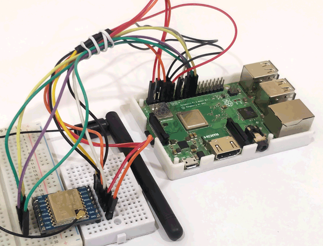
You can also use the circuit diagram below for reference. Note that the circuit diagram was created using the RFM9x module which is very similar to the SX1278 module, hence appearance might differ in the below image.

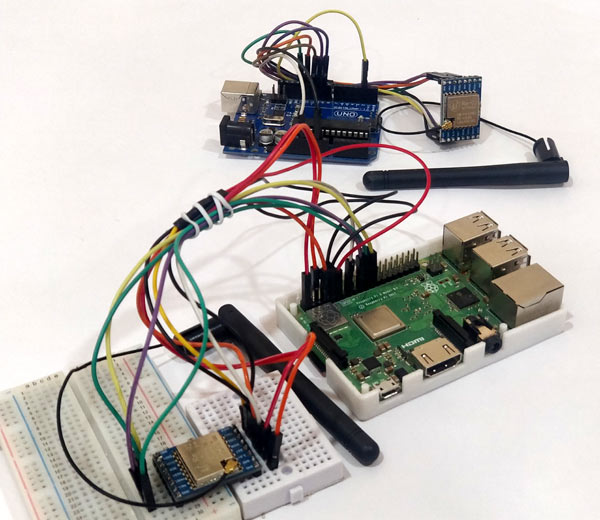
The connections are pretty straight forward, only problem you might face is that the SX1278 is not breadboard compatible hence you have to use connecting wires directly to make the connections or use two small breadboards as shown below. Also few people suggest to power the LoRa module with separate 3.3V power rail as the Pi might not be able to source enough current. However Lora being a low power module should work on the 3.3V rail of Pi, I tested the same and found it to be working without any problem. But, still take it with a pinch of salt. My connection set-up of LoRa with Raspberry pi looks something like this below
Connecting Arduino with LoRa
The connection for the Arduino module remains the same as that we used in our previous tutorial. The only difference will be instead of using the library from Sandeep Mistry we will use the Rspreal library based on Radio head which we will discuss later in this project. The circuit is give below
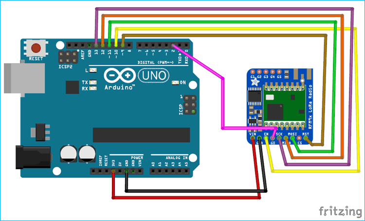
Again you can use the 3.3V pin on Arduino Uno or use a separate 3.3V regulator. In this project I have used the on-board voltage regulator. The pin connection table is given below to help you to make the connections easily.
| LoRa SX1278 Module | Arduino UNO Board |
| 3.3V | 3.3V |
| Gnd | Gnd |
| En/Nss | D10 |
| G0/DIO0 | D2 |
| SCK | D13 |
| MISO | D12 |
| MOSI | D11 |
| RST | D9 |
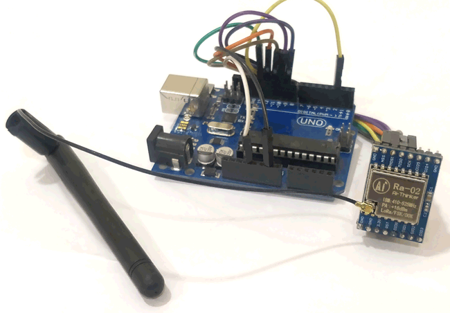
Since the module does not fit in a breadboard I have used the connecting wires directly to make the connections. Once the connection are made Arduino LoRa setup will look something like this below
pyLoRa for Raspberry Pi
There are many python packages that you can use with LoRa. Also commonly the Raspberry Pi is used as a LoRaWAN to get data from multiple LoRa nodes. But, in this project our aim to do Peer to Peer communication between two Raspberry Pi modules or between a Raspberry Pi and an Arduino. So, I decided to use the pyLoRa package. It has a rpsreal LoRa Arduino and rpsreal LoRa Raspberry pi modules which can be used on the Arduino and the Raspberry Pi environment. For now, let’s focus on the Raspberry Pi environment.
Configuring the Raspberry Pi for LoRa module
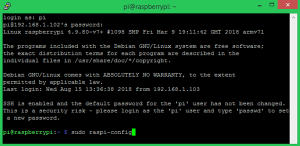
As told earlier the LoRa module works with SPI communication, so we have to enable SPI on Pi and then install the pylora package. Follow the below steps to do the same, after opening the terminal window of Pi. Again, I am using putty to connect to my Pi you can use your convenient method.
Step 1: Get into the configuration window using the following command. To get the below window
sudo raspi-config
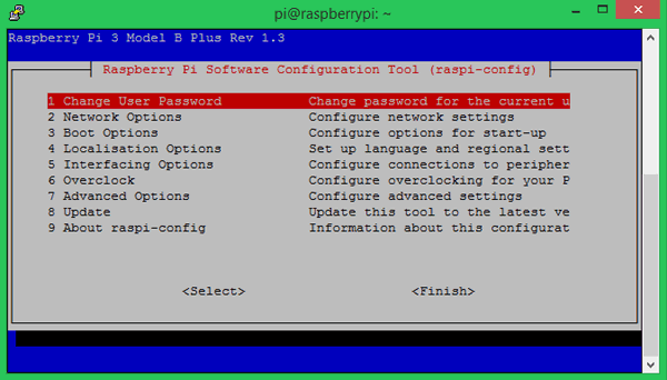
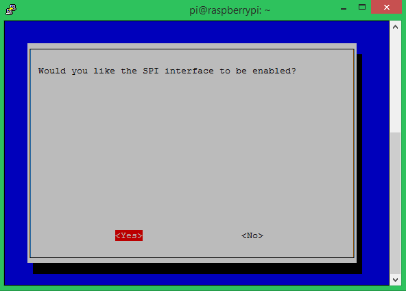
Step 2: Navigate to interfacing options and enable SPI as shown in the image below. We have to enable the SPI interface because as we discussed the LCD and PI communicates through SPI protocol
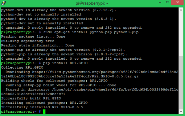
Step 3: Save the changes and get back to the terminal window. Make sure pip and python is updated and then install the RPi.GPIO package using the following command.
pip install RPi.GPIO
This package class will help us control the GPIO pin on the Pi. If successfully installed your screen will look like this
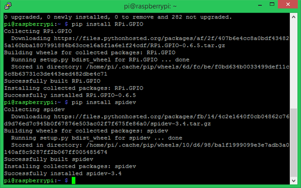
Step 4: Similarly proceed with installing the spidev package using the following command. Spidev is a python binding for Linux which can be used to perform SPI communication on Raspberry Pi.
pip install spidev
If the installation is successful the terminal should look something like this below.
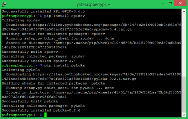
Step 5: Next lets install the pyLoRa package using the following pip command. This package installs the Radio models associated with LoRa.
pip install pyLoRa
If the installation is successful you will see the following screen.
The PyLoRa package also supports encrypted communication which can be used with Arduino and Raspberry Pi seamlessly. This will improve the data security in your communication. But you have to install separate package after this step which I am not doing since encryption is not in the scope of this tutorial. You can follow the above github links for more details.
After, this step you can add the package path information to pi and try with the python program given at the end. But I was not able to add the path successfully and hence had to manually download library and use the same directly for my programs. So I had to proceed with the following steps
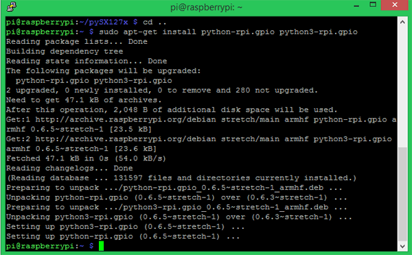
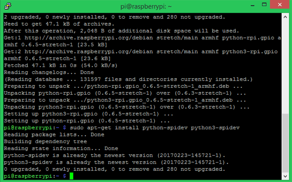
Step 6: Download and install the python-rpi.gpio package and spidev package using the below command.
sudo apt-get install python-rpi.gpio python3-rpi.gpio
sudo apt-get install python-spidev python3-spidev
The terminal window should display something like this after both the installations.
Step 7: Also install git and then use it to clone the python directory for our Raspberry Pi. You can do that using the following commands.
sudo apt-get install git
sudo git clone https://github.com/rpsreal/pySX127x
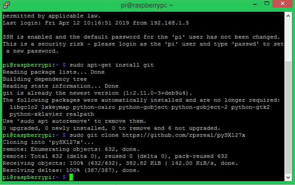
Once this step is complete you should find the SX127x sub directory in Raspberry Pi home folder. This will have all the required files associated with the library.

Programming Raspberry Pi for LoRa
In a peer to peer LoRa communication the module that is transmitting the information is called a server and the module that receives the information is called a client. In most cases the Arduino will be used in the field with a sensor to measure data and the Pi will be used to receive these data. So, I decided to use the Raspberry Pi as a client and the Arduino as a server in this tutorial. The complete Raspberry Pi client program can be found at the bottom of this page. Here I will try to explain the important lines in the program.
Caution: Make sure the program file is in the same directory where the SX127x library folder is present. You can copy this folder and use it anywhere if you wish to port the project.
The program is pretty simple we have to set the LoRa module to work in 433Mhz and then listen for incoming packets. If we receive anything we simple print them on the console. As always we begin the program by importing the required the python libraries.
from time import sleep
from SX127x.LoRa import *
from SX127x.board_config import BOARD
BOARD.setup()
In this case the time package is used to create delays, the Lora package is used for LoRa communication and the board_config is used to set the board and LoRa parameters. We also setup the board using the BOARD.setup() function.
Next we create the python LoRa class with three definitions. Since we only indent to make the program work as a raspberry client the class has only three functions namely the init class, start class and on_rx_done class. The init class initializes the LoRa module in 433MHz with 125kHz bandwidth as set in the set_pa_config method. Then it also puts the module in sleep mode to save power consumption.
#  Medium Range  Defaults after init are 434.0MHz, Bw = 125 kHz, Cr = 4/5, Sf = 128chips/symbol, CRC on 13 dBm
lora.set_pa_config(pa_select=1)

    def __init__(self, verbose=False):
        super(LoRaRcvCont, self).__init__(verbose)
        self.set_mode(MODE.SLEEP)
        self.set_dio_mapping([0] * 6)
The start function is where we configure the module as receiver and obtain like RSSI (Receiving signal strength Indicator), status, operating frequency etc. We set the module to work in continuous receiver mode (RXCONT) from sleep mode and then use a while loop to read values like RSSI and modem status. We also flush the data in the serial buffer onto the terminal.
    def start(self):
        self.reset_ptr_rx()
        self.set_mode(MODE.RXCONT)
        while True:
            sleep(.5)
            rssi_value = self.get_rssi_value()
            status = self.get_modem_status()
            sys.stdout.flush()
Finally the on_rx_done function gets executed after the incoming packet is read. In this function the received values is moved into a variable called payload from the Rx buffer after setting the receiving flag high. Then the received values are decoded with utf-8 to print a user readable data on the shell. We also put the module back in sleep mode till another value is received.
    def on_rx_done(self):
        print("\nReceived: ")
        self.clear_irq_flags(RxDone=1)
        payload = self.read_payload(nocheck=True)
        print(bytes(payload).decode("utf-8",'ignore'))
        self.set_mode(MODE.SLEEP)
        self.reset_ptr_rx()
        self.set_mode(MODE.RXCONT)
The remaining part of the program is just to print the received values on the console and terminate the program using a keyboard interrupt. We again set the board in sleep mode even after termination of the program to save power.
try:
    lora.start()
except KeyboardInterrupt:
    sys.stdout.flush()
    print("")
    sys.stderr.write("KeyboardInterrupt\n")
finally:
    sys.stdout.flush()
    print("")
    lora.set_mode(MODE.SLEEP)
    BOARD.teardown()
Arduino Code for LoRa to communicate with Raspberry Pi
As I mentioned earlier the rpsreal code supports both Arduino and Pi and hence communication between Arduino and Pi is possible. It works based on the Radiohead Library from AirSpayce’s. So you have to install the radio head library first to your Arduino IDE.
To do that visit the Github page and download the library in ZIP folder. Then place it in the library folder of your Arduino IDE. Now, restart the Arduino IDE and you will find example files for Radio head library. Here we will program the Arduino to work as a LoRa server to send test packets like 0 to 9. The Complete code to do the same can be found at the bottom of this page as always. Here, I will explain few important lines in the program.
We begin the program by importing the SPI library (installed by default) to use SPI protocol and then the RH_RF95 library from Radio head to perform LoRa communication. Then we define to which pin of Arduino we have connected the Chip select (CS), Reset (RST) and Interrupt (INT) pin of the LoRa with Arduino. Finally we also define that the module should work in 434MHz Frequency and initialize the LoRa module.
#include <SPI.h> //Import SPI librarey
#include <RH_RF95.h> // RF95 from RadioHead Librarey

#define RFM95_CS 10 //CS if Lora connected to pin 10
#define RFM95_RST 9 //RST of Lora connected to pin 9
#define RFM95_INT 2 //INT of Lora connected to pin 2

// Change to 434.0 or other frequency, must match RX's freq!
#define RF95_FREQ 434.0

// Singleton instance of the radio driver
RH_RF95 rf95(RFM95_CS, RFM95_INT);
Inside the setup function we will reset the LoRa module by pulling its reset pin to low for 10 milli second to start fresh. Then we initialize it with the module that we created earlier using Radio head library. Then, we set the frequency and transmission power for the LoRa server. Higher the transmission more distance your packets will travel but will consume more power.
void setup()
{
//Initialize Serial Monitor
  Serial.begin(9600);

// Reset LoRa Module
  pinMode(RFM95_RST, OUTPUT);
  digitalWrite(RFM95_RST, LOW);
  delay(10);
  digitalWrite(RFM95_RST, HIGH);
  delay(10);

//Initialize LoRa Module
  while (!rf95.init()) {
    Serial.println("LoRa radio init failed");
    while (1);
  }


 //Set the default frequency 434.0MHz

  if (!rf95.setFrequency(RF95_FREQ)) {
    Serial.println("setFrequency failed");
    while (1);
  }
  rf95.setTxPower(18); //Transmission power of the Lora Module
}
Inside the infinite loop function, we simply have to send the data packet through the LoRa module. This data can be anything like sensor value of user command. But for simplicity we will send char value 0 to 9 for every 1 second interval and then initialize the value back to 0 after reaching 9. Note that the values can be sent only in a char array format and the type of data should be unit8_t that is 1 byte at a time. The code to do the same is shown below
void loop()
{
  Serial.print("Send: ");
  char radiopacket[1] = char(value)};
  rf95.send((uint8_t *)radiopacket, 1);

  delay(1000);
  value++;
  if (value > '9')
  value = 48;
}
Testing LoRa Communication between Raspberry Pi and Arduino
Now, that we got both our hardware and program ready we simply have to upload the Arduino code to the UNO board and the python sketch should be launched on pi. My test set-up with both the hardware connected, looks something like this below
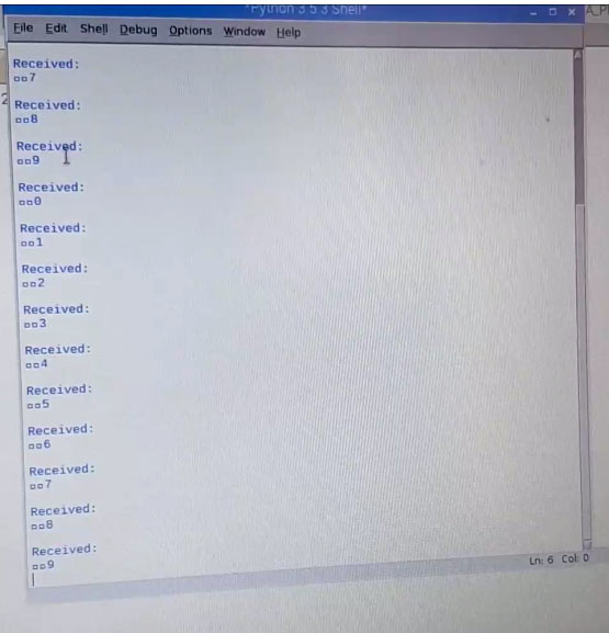
Once the python client sketch is launched on the Pi (use only python 3), if everything is working properly you should see the Arduino packets received in pi though the shell window. You should notice “Received: 0” to 9 like shown in the image below.
The complete Raspberry pi code with all the required libraries can be downloaded from here.
You can now move the Arduino server and check the range of the module; it is also possible to display the RSSI value on the shell if required. The complete working of the project can be found in the video linked below. Now, that we know how to establish long distance low power LoRa communication between Arduino and Raspberry pi we can proceed with adding sensor on Arduino side and cloud platform on Pi side to make a complete IoT package.
Hope you understood the project and enjoyed building it. If you have problem in getting it to work, use the comment section below or the forums for other technical quires.
Complete Project Code
Lora Receiver Code for Raspberry Pi: (Download the required libraries from here)
from time import sleep
from SX127x.LoRa import *
from SX127x.board_config import BOARD
BOARD.setup()
class LoRaRcvCont(LoRa):
    def __init__(self, verbose=False):
        super(LoRaRcvCont, self).__init__(verbose)
        self.set_mode(MODE.SLEEP)
        self.set_dio_mapping([0] * 6)
    def start(self):
        self.reset_ptr_rx()
        self.set_mode(MODE.RXCONT)
        while True:
            sleep(.5)
            rssi_value = self.get_rssi_value()
            status = self.get_modem_status()
            sys.stdout.flush()

    def on_rx_done(self):
        print("\nReceived: ")
        self.clear_irq_flags(RxDone=1)
        payload = self.read_payload(nocheck=True)
        print(bytes(payload).decode("utf-8",'ignore'))
        self.set_mode(MODE.SLEEP)
        self.reset_ptr_rx()
        self.set_mode(MODE.RXCONT)
lora = LoRaRcvCont(verbose=False)
lora.set_mode(MODE.STDBY)
#  Medium Range  Defaults after init are 434.0MHz, Bw = 125 kHz, Cr = 4/5, Sf = 128chips/symbol, CRC on 13 dBm
lora.set_pa_config(pa_select=1)
try:
    lora.start()
except KeyboardInterrupt:
    sys.stdout.flush()
    print("")
    sys.stderr.write("KeyboardInterrupt\n")
finally:
    sys.stdout.flush()
    print("")
    lora.set_mode(MODE.SLEEP)
    BOARD.teardown()

Lora Server Code for Arduino:
//Arduino Raspberry Pi wireless Comunnication through LoRa - SX1278
//Send 0 to 9 from Arduino through Radio head LoRa without ACK
//Dated: 19-4-20198
#include <SPI.h> //Import SPI librarey
#include <RH_RF95.h> // RF95 from RadioHead Librarey
#define RFM95_CS 10 //CS if Lora connected to pin 10
#define RFM95_RST 9 //RST of Lora connected to pin 9
#define RFM95_INT 2 //INT of Lora connected to pin 2
// Change to 434.0 or other frequency, must match RX's freq!
#define RF95_FREQ 434.0
// Singleton instance of the radio driver
RH_RF95 rf95(RFM95_CS, RFM95_INT);
void setup()
{

//Initialize Serial Monitor
  Serial.begin(9600);

// Reset LoRa Module
  pinMode(RFM95_RST, OUTPUT);
  digitalWrite(RFM95_RST, LOW);
  delay(10);
  digitalWrite(RFM95_RST, HIGH);
  delay(10);
//Initialize LoRa Module
  while (!rf95.init()) {
    Serial.println("LoRa radio init failed");
    while (1);
  }

 //Set the default frequency 434.0MHz
  if (!rf95.setFrequency(RF95_FREQ)) {
    Serial.println("setFrequency failed");
    while (1);
  }
  rf95.setTxPower(18); //Transmission power of the Lora Module
}
char value = 48;
void loop()
{
  Serial.print("Send: ");
  char radiopacket[1] = char(value)};
  rf95.send((uint8_t *)radiopacket, 1);

  delay(1000);
  value++;
  if (value > '9')
  value = 48;
}
Comments
Wonderful information.
I am using RAK831 Pilot gateway. Do I need to do the same process and use the same coding that you have used? Please advise..
Thanks
Hi Sonam,
The tutorial shown here is for peer to peer communication. you cannot use the same method if you are trying to communicate between a Node and a Gateway. I do not have a gateway with me yet. Once I get one will post a tutorial on that as well. I am still looking for the best gateway to buy
Warning (from warnings module):
File "/home/pi/Downloads/LORA_PI_RX/SX127x/board_config.py", line 61
GPIO.setup(BOARD.LED, GPIO.OUT)
RuntimeWarning: This channel is already in use, continuing anyway. Use GPIO.setwarnings(False) to disable warnings.
Warning (from warnings module):
File "/home/pi/Downloads/LORA_PI_RX/SX127x/board_config.py", line 62
GPIO.setup(BOARD.RST, GPIO.OUT)
RuntimeWarning: This channel is already in use, continuing anyway. Use GPIO.setwarnings(False) to disable warnings.
after this nothing will get...
I try both on 434 and 868 ...because I have dragging device embedded on arduino..but try to replace Arduino with raspberry pi
Superb Tutorial machan, really helpful.
proud of you da.
I think there is a mistake in this part of the Arduino sketch code (underlined) causing a compile error:
{
Serial.print("Send: ");
char radiopacket[1] = char(value)};
rf95.send((uint8_t *)radiopacket, 1);
delay(1000);
value++;
if (value > '9')
value = 48;
}
i got a Error pls help me U send a Arduino code and 868Mhz LoRa also work same code??
please answer the question
Hi,
My Arduino Error is Clear But the Raspberry pi not Receive a Data
Spent a week trying to debug this procedure but it just does not work with SX1276 on RPi 3b and RFM95W module on Arduino Uno both at 913.8 MHz. Tried changing frequencies, etc., but nothing.
Sorry, but this published procedure has failed for me. Giving up and moving on.
can i use other SX1278 modules, E32 TTL 1W? Thanks.
I am try to change frequency of LoRa from 434MHz to 867MHz but i could not.
Please suggest me, how to change it.
How to change frequency if lora from 434MHz to 867MHz
compiling error in code...pls check
Hey all
I see that a bunch of people haven't had much luck getting this working - probably due to the huge number of variables.
I have gotten my arduino to compile, there was indeed a missing bracket. This seems to work:
void loop()
{
  Serial.print("Send: ");
  char radiopacket[1] = {char(value)};
  rf95.send((uint8_t *)radiopacket, 1);


  delay(1000);
  value++;
  if (value > '9')
  value = 48;
}
However after Uploading to the Arduino I'm getting the following error in my console:
LoRa radio init failed
Which is pretty self descriptive. However I'm at a loss for why it failed or how to remedy this. If anyone's gotten the above project working, please let me know!
-Josh
Hi all
The above bracket did fix the arduino code. The correct line is:
char radiopacket[1] = {char(value)};However it currently sends only 1-2 packets of data before stopping for reasons unknown:
Received:

0

Received:

1
I am maybe suspecting a radio issue..? But I have no way of debugging of testing that theory. I have successfully had it count up to 9 and cycle back to 0 one time, although I have no idea what caused it to suddenly work, and I've not been able to replicate that behavior a second time.
Hi,
I have uploaded the same code.
The code works fine till "def start(self)".
But, is in not entering "on_rx_done(self)". I am not recieveing any packets.
how can I send dht11 sensor data from Arduino to Raspberry Pi using SX1278 433MHz LoRa Module?
Help me out with programming codes!!
Can i do the same thing but in reverse ? With Pi as Sender and Arduino as Receiver? How to program Pi for that?
this guide only works with 433MHz, if you want something other use the example code in the library(
https://github.com/rpsreal/pySX127x), its more detailed and works perfectly.
I have successfully implemented this on a Pi Zero (Freq=917MHz, Sync Word=0x12) with a range of Arduino and 'compatible' MCUs sending data from BME sensors, although my Arduino and 'compatible' MCUs are running different software.
What I would like to know, if anyone is answering questions about this setup, is that it appears that, while the hardware configuration for the Raspberry Pi shows conenctions for four DIO pins, they do not appear to be configured in the software, which sugegsts that they are not actually being used. Does anyone know if this is the case, and perhpas more specifially, how one specifies DIO pin numbers in the relevant method call:
```
self.set_dio_mapping{[0] *6}
```
As written, this looks like the mappings are all zero, rather than to pins 4, 16, 17 & 27 respectively, as per the hardware configuration.
Thanks
Hi! Im using your code but have some problems to send an ACK back to the sender. The important part of my code looks like this:
def on_rx_done(self):
....
print("Data received, now send ACK.")
self.write_payload([0x0f, 65, 67, 75])
self.set-mode(MODE.TX)
print("done")
sleep(1)
self.reset_ptr_rx()
self.set_mode(MODE.RXCONT)
def on_tx_done(self):
print("TX done")
The Raspberry receives the data correct and also sends an ACK which is recognised by the Arduino, but the "TX done" is never shown.
My idea was to move tha part after the "sleep(1)" into the tx_done function.
Without the sleep(1) no ACK is sent.
Can anyone tell me why the tx_done function is never executed or why I need the sleep(1)? Thanks!
Hi @Philipp
I managed to enter the tx_done function by executing the following
self.set_dio_mapping([1,0,0,0,0,0])
I'm not sure why this allowed me to enter into the function though, and more importantly, I am not able to receive the data on the arduino side.
Would you have any tips to offer me?
Thanks in advance!
traceback hist recent call last): FLle hone /pesktop/LORA PI RXLORA PI
MeraLakaRCyCent(verbose False) tine 32, in <module Fl lehdne/1 Desktop LORA PI RX/LORA PI RX: py", Line 9, In it
RX. py,
supet(LeRaRevCent, self) init_(verbose) 1 /Desktop/LORA PT RX/SX127x/LORa py, line 95, in inat BOARDad everts(selr ise, self. dioi, se lt dio2, setr, dioa, setr. dio4,
Pale home pubesktop/LORA PERX/SX127x/board. contig py n e 105. maddes ent BOARD da avant de rect(BOARD DIOD, catback 2.0 )
tehomeou Desktop LDRA PIRK/8x127x/board config.py", line te in adoe
erit detect
GPIO add event de tett (dio uber, GPIO RISING, callback callback
RuntimeError Failed to add edge detection.
im getting this error whenever i run code in raspberrypi.
Hi,
I am trying to build up a lora communication , created own gateway based on pi and using sx1278 lora module.
I am able to send sensor data from arduino/esp32 with lora module(sx1278) at raspberry pi(gatgeway) but not able to transmit (downlink) data from pi to node.
Open for the suggestions and feedback.
Looking forward for response.
what is the range i can use these devices apart ?
can't pi resend back to uno?

I tried this with exact setup and it works. How do I make this work with sync word?