
In today’s world Bluetooth has become very popular and almost every device like mobile phone, laptop, and cars infotainment system uses Bluetooth for wireless communication. Bluetooth is not only used to transfer data but also to control another Bluetooth devices wirelessly, like using Bluetooth headset you can hear the song wirelessly from your mobile phone or can use car audio system to play the songs from your mobile.
Bluetooth is a wireless technology that works on the frequency of 2.4GHz. Normal Bluetooth signal is in range of 10 meter radius. Bluetooth is most commonly used wireless technology in embedded projects provided that the range of communication is limited. Bluetooth has added advantage of its low power consumption and low cost operation. It is generally used for interfacing microcontrollers with Smart Phones by using Bluetooth applications.
We have seen interfacing of Bluetooth module with other microcontrollers like Arduino, 8051, PIC etc. Now in this tutorial we will interface a HC-05 Bluetooth module with STM32F103C8 and Turn ON/OFF a LED using Android mobile.
Materials Required
- STM32F103C8
- Bluetooth Module (HC-05)
- LED
- Android Mobile
- Breadboard
- Connecting wires
Software:
- Bluetooth Terminal (Android Application)
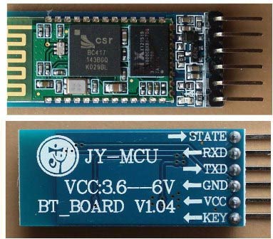
Bluetooth Module (HC-05)
It is mostly used Bluetooth module in embedded projects. It is a serial Bluetooth module that uses serial communication having range less than 100m and operates at 5V (3.3V minimum). It can be used to connect two microcontrollers wirelessly and also with mobile phone and laptops. As there are many android applications are available, it is very useful for making wireless Bluetooth controlled projects.
It uses USART communication and can be interfaced with microcontrollers having USART communication protocol.
It has an integrated antenna. It has Master/Slave configurations that can be changed in AT command mode that is useful when only one device should send the data (master to slave) like for example from PC (MASTER) to slave (any MCU). A master can connect to other devices and slave doesn’t connect to other connection other than master.
Modes of Operation
It has two modes AT Command Mode & Data Mode.
When Bluetooth is powered up it enters data mode default. This mode can be used for data transfers. To enter into AT Command mode during power up we need to press the button present in module to change the default settings of the module like master/slave configurations.
Pins of Bluetooth Module
- EN pin (ENABLE) -This pin is used to set Data Mode or AT Command Mode. By default it is in DATA MODE. When button pressed during power up it goes to AT command mode.
- +5V pin - This is used for power supply to the module
- GND pin - This is used for ground for module
- TX pin - This pin to connected to RX pin of MCU
- RX pin - This pin connected to TX pin of MCU
- STATE - This pin indicates the status of the module, see below about indications
LED Indication
- It has a LED (RED) indicator which provides the state of the Bluetooth module.
- When the Bluetooth module is NOT CONNECTED to any device the signal goes low and red led blinks continuously which indicate module is NOT PAIRED.
- When Bluetooth module is CONNECTED to any device the signal goes HIGH and red led blinks with some delay which indicates module is PAIRED.
Check our other projects to learn more about Bluetooth module HC-05 with other microcontrollers:
- Bluetooth Controlled Toy Car using Arduino
- Bluetooth Controlled Home Automation System using 8051
- Voice Controlled Lights using Raspberry Pi
- Smart Phone Controlled FM Radio using Arduino and Processing
- Mobile Phone Controlled Robot Car using G-Sensor and Arduino
- Interfacing Bluetooth Module HC-06 with PIC Microcontroller
STM32 USART Ports
STM32F103C8 (BLUE PILL) USART serial communication ports are shown in the pin out image below. These are blue coloured having (PA9-TX1, PA10- RX1, PA2-TX2, PA3- RX2, PB10-TX3, PB11- RX3). It has three such communication channels.

Circuit Diagram and Connections
The circuit connections for interfacing Bluetooth Module with STM32 are made like below

Connection between STM32F103C8 & Bluetooth module (HC-05)
- The TX pin (PA9) of the STM32F103C8 is connected to the RX pin of the Bluetooth module.
- The RX pin (PA10) of the STM32F103C8 is connected to the TX pin of the Bluetooth module.
- VCC (+5V) pin of Bluetooth module is connected to 5V pin of STM32F103C8.
- GND pin of Bluetooth module is connected to GND pin of STM32F103C8.
Other Connections
- The (PA0) pin of STM32 (Blue Pill) is connected to positive pin of LED through a series resistor. The LED is used here is mixed colour.
- The led another pin is connected to GND of STM32.
Programming STM32F103C8
Interfacing Bluetooth with STM32 is same as arduino and programming in STM32 is same as Arduino IDE. See this tutorial for programming STM32 with USB using Arduino IDE.
As already told, in this project, we will interface a (HC-05) Bluetooth module with STM32F103C8 and use a Android Smart Phone with Bluetooth Terminal android application to turn ON and OFF the LED.
Note: The RX & TX pin must be removed while uploading the code to STM32F103C8.
Complete code for this project is given at the end of this tutorial with a demonstration Video.
Coding for this project is so simple. Same Arduino codes can be used but only the pin should be changed. Because we have three sets of USART pin in STM32F103C8 so we must specify the correct pin that we used to connect the Bluetooth module.
1. First we need to name the pins with their respective pin number with int data type as follows
const int pinout = PA0;
2. Next we need have a variable to store serial data from the android mobile. The data can be a char or integer as follows
char inputdata = 0;
3. Next in void setup(), we must start serial communication between STM32 Blue Pill and the Bluetooth module by giving baud rate of 9600
Serial1.begin(9600);
We used Serial1 here because we connected HC-05 to TX1 and RX1 of STM32.
We can also use Serial2 or Serial3 but accordingly pin must be connected.
4. An intro message is sent as serial data to the serial1, that is to Bluetooth module HC05. This module further send data to the Bluetooth Terminal app of android mobile. So we use below statements
Serial1.print("CIRCUIT DIGEST\n");
Serial1.print("BLUETOOTH WITH STM32\n");
5. Next we need to set the pinmode (PA0) as output , as we connected led to this pin.so we use
pinMode(pinout, OUTPUT);
6. Next in the void loop (), we run following data to read the serial data and turn on/off the LED accordingly
void loop()
 {
   If (Serial1.available() > 0)
   {
      inputdata = Serial1.read();
      if(inputdata == '1')
      {
         digitalWrite(pinout, HIGH);
         Serial1.print("LED ON\n");
      }

      else if(inputdata == '0')
      {
         digitalWrite(pinout, LOW);
         Serial1.print("LED OFF\n");
      }
   }
}
Here we use if statement because these code only executes when Serial1 port has any data received from the Bluetooth module that why this statement is used Serial1.available() > 0 . Otherwise if it won’t get into, it waits until it starts serial communication. Now it stores the received data in a variable inputdata = Serial1.read(). Then it check the value sent from Bluetooth terminal app. So if value is 1, it prints LED ON and makes the pin (PA0) go HIGH by statement digitalWrite(pinout,HIGH) and if the value is 0, it prints LED OFF and makes (PA0) pin go LOW.

Steps for Connecting Bluetooth Module with Android Phone
Step 1:- Open Bluetooth from mobile after uploading code into STM32 from Arduino IDE and giving power to circuit. REMEMBER to remove RX and TX pin while UPLOADING code
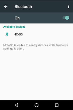
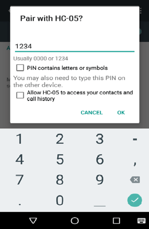
Step 2:- In available devices select HC-05 and enter password as 1234
Step 3:- After pairing, open Bluetooth Terminal app and select connect a device and select HC-05 as shown below
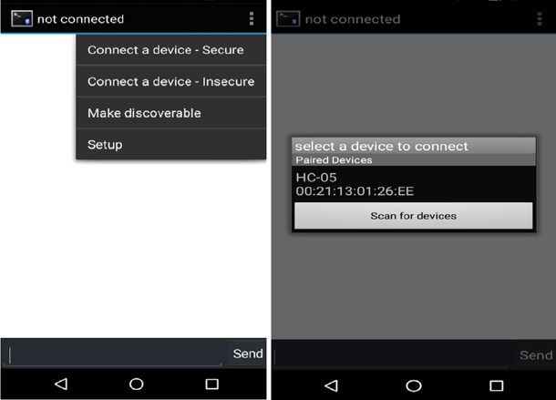
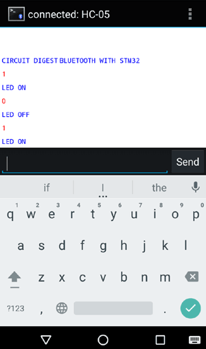
Step 4:- After connecting with HC-05 Bluetooth Module, provide values in the terminal 1 or 0 to turn ON and OFF the LED. You will also receive a message that LED is On or Off.
Complete Project Code
//PROGRAM FOR BLUETOOTH INTERFACE WITH STM32F103C8

//CIRCUIT DIGEST

//Pramoth Thangavel
const int pinout = PA0; // declare pinout with int data type and pin value

char inputdata = 0;  //Variable for storing received data
void setup()

{

    Serial1.begin(9600);                      //Sets the baud rate for bluetooth pins

    Serial1.print("CIRCUIT DIGEST\n");

    Serial1.print("BLUETOOTH WITH STM32\n");

    pinMode(pinout, OUTPUT);                  //Sets digital pin PA0 as output pin for led

}
void loop()

{

   if(Serial1.available() > 0)      // Send data only when you receive data:

   {

      inputdata = Serial1.read();        //Read the incoming data & store into data


      if(inputdata == '1')

      {

         digitalWrite(pinout, HIGH);

         Serial1.print("LED ON\n");

      }


      else if(inputdata == '0')

      {

         digitalWrite(pinout, LOW);

         Serial1.print("LED OFF\n");

      }

   }

}

Hi Pramoth,
Good article, but it would be nice if you explained what Serial1, Serial2 and Serial3 correspond to. Do they refer to each of the USART ports?
Cheers,
Jay