
In the previous tutorial we learned about Modbus RS-485 Serial Communication with Arduino as Slave. In continuation with that article today Arduino will be used MODBUS Master and communicate with MODBUS slave. Here MODBUS Slave Software installed computer will be used as MODBUS Master. So, let’s begin by a short introduction about the RS-485 and Modbus.
RS-485 Serial Communication
RS-485 is an asynchronous serial communication protocol which doesn’t not require clock. It uses a technique called differential signal to transfer binary data from one device to another. It provides a Half-Duplex communication when using two wires and Full-Duplex requires 4 fours wires.
Connecting RS-485 with Arduino
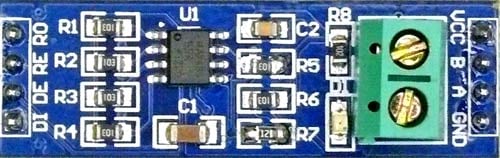
RS-485 Module can be connected to any microcontroller having serial port. For using RS-485 module with microcontrollers, a module called 5V MAX485 TTL to RS485 which is based on Maxim MAX485 IC is needed as it allows serial communication over long distance of 1200 meters. It is bidirectional and half duplex and has data transfer rate of 2.5 Mbps. This module requires a voltage of 5V.
Pin-Out of RS-485:
| Pin Name | Use |
| VCC | 5V |
| A | Non-inverting Receiver Input Non-Inverting Driver Output |
| B | Inverting Receiver Input Inverting Driver Output |
| GND | GND (0V) |
| R0 | Receiver Out (RX pin) |
| RE | Receiver Output (LOW-Enable) |
| DE | Driver Output (HIGH-Enable) |
| DI | Driver Input (TX pin) |
USB to RS-485 Converter Module:
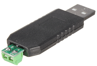
This is an USB to RS485 Converter Adapter module which supports WIN7, XP, Vista, Linux, Mac OS and provides an easy to use RS485 interface by means of using COM port in the computer. This module is plug-and-play device. There are no command structures, whatever is sent to the Virtual COM Port is automatically converted to RS485 and vice versa. The module is completely self-powered from the USB bus. So, no need of external power supply for operation.
It shows up as a Serial/COM port and is accessible from applications or hyper-terminal. This converter provides half-duplex RS-485 communication. The Baud rate range is 75 bps to 115200 bps, maximum up to 6 Mbps.
To use this device there are various Modbus Software available in the internet. In this tutorial software called Modbus Slave software from Witte Software is used. The software can be downloaded from the website www.modbustools.com.
Modbus Slave Software
Modbus Slave application receives values from any Modbus Master device by using serial communication port. It is a data communication test software. Before using the software, following things must be known. For more information, refer software manual.
Slave ID:
Each slave in a network is assigned a unique unit address from 1 to 127. When the master requests data, the first byte it sends is the Slave address. This way each slave knows after the first byte whether or not to ignore the message.
Modbus Registers:
Discrete Output Coils: It is a 1-bit register and they are used to control discrete outputs and can be read or written. They have register numbers from (1 to 9999).
Discrete Input: It is a 1-bit register and used as inputs and can only be read. They have register numbers from (10001 to 19999).
Input Register: It is a 16-bit register used for input and can only be read. They have register numbers from (30001 to 39999).
Holding Register: It is a 16-bit register and can be read or written. They have register numbers from (40001 to 49999).
Modbus Function codes:
| Function Code | Action | Table Name |
| 04 (04 hex) | Read | Analog Input Registers |
| 03 (03 hex) | Read | Analog Output Holding Registers |
| 06 (06 hex) | Write single | Analog Output Holding Register |
| 16 (10 hex) | Write multiple | Analog Output Holding Registers |
|
Function Code |
Action |
Table Name |
|
02 (02 hex) |
Read |
Discrete Input Contacts |
|
01 (01 hex) |
Read |
Discrete Output Coils |
|
05 (05 hex) |
Write single |
Discrete Output Coil |
|
15 (0F hex) |
Write multiple |
Discrete Output Coils |
CRC stands for Cyclic Redundancy check. It is two bytes added to the end of every Modbus message for error detection.
Components Required
Hardware
- Arduino UNO
- MAX-485 TTL to RS-485 Converter Module
- USB to RS-485 Converter Module
- Push Buttons (2)
- 10k-Resistor (2)
- 16x2 LCD display
- 10k Potentiometer
Software
Circuit Diagram

Circuit Connections between MAX-485 TTL to RS-485 converter module and Arduino UNO:
|
Arduino UNO |
MAX-485 TTL to RS-485 Converter Module |
|
0(RX) |
RO |
|
1(TX) |
DI |
|
3 |
DE |
|
2 |
RE |
|
+5V |
VCC |
|
GND |
GND |
Circuit Connections between MAX-485 TTL to RS-485 Module and USB to RS-485 converter:
|
MAX-485 TTL to RS-485 Converter Module |
USB to RS-485 Module Connected with PC |
|
A |
A |
|
B |
B |
Circuit Connections between Arduino UNO and 16x2 LCD display:
|
16x2 LCD |
Arduino UNO |
|
VSS |
GND |
|
VDD |
+5V |
|
V0 |
To potentiometer centre pin for contrast control of LCD |
|
RS |
8 |
|
RW |
GND |
|
E |
9 |
|
D4 |
10 |
|
D5 |
11 |
|
D6 |
12 |
|
D7 |
13 |
|
A |
+5V |
|
K |
GND |
Two Push Buttons with Pull down resistor of 10k are also connected to the Arduino Pins 4 and 5. A 10K potentiometer is used to provide Analog input value to the Arduino pin A0.
After the circuit connections the complete setup looks like this.
Programming Arduino Uno as MODBUS Master
In this tutorial the Arduino Uno is configured as Modbus Master by using Master Modbus Arduino coding with the help of Modbus Master library. Here Arduino Uno has two push buttons and a potentiometer to send the values from Modbus Master Arduino to Modbus Slave software.
For using Modbus in Arduino UNO, a library <ModbusMaster.h> is used. This library is used for communicating with RS-485 Modbus Master or Slave via RTU protocol. Download the Modbus Master and add the library in the sketch by following Sketch->include library->Add .zip Library.
Complete program with a detailed video is given at the end. Here we have explained has some major steps below.
First, include the ModbusMaster and Liquid Crystal Library:
#include <ModbusMaster.h>
#include <LiquidCrystal.h>
Next define the Pin names that are connected between the MAX485 TTL to RS-485 converter module and Arduino UNO.
#define MAX485_DE      3
#define MAX485_RE_NEG  2
Initialize node object for class ModbusMaster.
ModbusMaster node;
Then write two functions preTrasnmission() and postTrasmission() for making the Pins RE and DE of Max485 TTL to RS-485 convertor module high or low to Transmit or Receive data.
void preTransmission()
{
  digitalWrite(MAX485_RE_NEG, 1);
  digitalWrite(MAX485_DE, 1);
}
void postTransmission()
{
  digitalWrite(MAX485_RE_NEG, 0);
  digitalWrite(MAX485_DE, 0);
}
Next in the void setup (), the LCD is set in 16x2 mode and a welcome message is displayed and cleared.
  lcd.begin(16,2);
  lcd.print("CIRCUIT DIGEST");
  delay(3000);
  lcd.clear();
  lcd.print("Arduino");
  lcd.setCursor(0,1);
  lcd.print("Modbus Master");
  delay(3000);
  lcd.clear();
Then RE and DE pins are set as OUTPUT pins and the pins 4 & 5 are set as INPUT pins (Push Buttons).
  pinMode(MAX485_RE_NEG, OUTPUT);
  pinMode(MAX485_DE, OUTPUT);

  pinMode(4,INPUT);
  pinMode(5,INPUT);
Initially the DE and RE pins of the MAX-485 TTL to RS-485 Converter Module is set LOW
  digitalWrite(MAX485_RE_NEG, 0);
  digitalWrite(MAX485_DE, 0);
Set the baud rate at 115200 and inform the Modbus Master with the slave ID 1.
Serial.begin(115200);
node.begin(1, Serial);
After that call back statements are used so that the RS-485 Transceiver is configured properly.
  node.preTransmission(preTransmission);
  node.postTransmission(postTransmission);
Now in the void loop()
- First the Analog value is read from the pin A0 that is connected with potentiometer.
float value = analogRead(A0);
- Then ADC value of (0 to 1023) is written to the 0x40000 register for sending it to Modbus Slave by using the following statement.
node.writeSingleRegister(0x40000,value);
- Then the value is also displayed in the 16x2 LCD display
  lcd.setCursor(0,0);
  lcd.print("POT Val :");
  lcd.print(value);
- Next the state of the two-push buttons is read.
  int a= digitalRead(4);
  int b= digitalRead(5);
- And depending upon the state of the push button, the value 0x40001 for button 1 and 0x40002 for button 2 is written to the Modbus Slave and also displayed on LCD display.
  if (a == 1)
  {
    node.writeSingleRegister(0x40001,1);
    lcd.setCursor(0,1);
    lcd.print("S1: 1");
  }
  else
  {
    node.writeSingleRegister(0x40001,0);
    lcd.setCursor(0,1);
    lcd.print("S1: 0");
  }
  if (b == 1)
  {
    node.writeSingleRegister(0x40002,1);
    lcd.setCursor(8,1);
    lcd.print("S2: 1");
  }
  else
  {
    node.writeSingleRegister(0x40002,0);
    lcd.setCursor(8,1);
    lcd.print("S2: 0");
  }

Testing the Arduino UNO as RS485 MODBUS Master
After the circuit connections are completed and the code is uploaded to Arduino Uno now its time to connect the USB to RS-485 Module to the PC where the Modbus Slave Software is installed.
Note: Open the device manager and check the COM port according to your PC where the USB to RS-485 Module is connected and then open the Modbus Slave software.
1.The Modbus Slave Tool appears as below and it indicates No Connection.

2. Next Open Connection->Connect and it appears as below.

3. It shows the below dialog box as this software is a trial version so click on Register Later

4. This trial software only runs for 10 minutes after opening it.

5. The connection details are shown below. Set Connection as Serial Port and Serial settings as respected COM port where USB to RS-485 module is connected. Then set the Baud rate as 115200 (As I used in Arduino Code), Data bits as 8, None Parity, 1 Stop Bits and Mode as RTU and then click OK.

6. Note that No connection disappears and now open Setup->Slave Definition.

7. Now enter the Slave ID as 1 and function as 03 Holding Register and address 0 and then click OK.

8. After that verify the ID as 1 and F as 03. In this tutorial first three registers are used (0-Potentiomter ADC value,1-Push button value,2-Push button value).

9. Now when Push button 2 is pressed. Note the value 1 in the third row. As push button 1 is not pressed it remains 0 in second row and in first row some pot value is displayed.

10. When Push button 1 is pressed. Note the value 1 in the second row. And as push button 2 is not pressed so it remains 0 in third row and in first row some pot value is displayed.

11. Now when both the Push Buttons are Pressed, there are value 1 in both rows second and third and also note the potentiometer value.

12. When potentiometer is varied, the Row 1 also varies in the Modbus Slave software.

This is how a RS-485 Modbus can be used in serial communication with the Arduino UNO as Master. Check the previous tutorial to see Arduino Uno as slave in MODBUS commination.
Find the complete code and a Demonstration video below
Complete Project Code
#include <ModbusMaster.h>               //Library for using ModbusMaster
#include <LiquidCrystal.h>              //Library for using LCD display
#define MAX485_DE      3
#define MAX485_RE_NEG  2
ModbusMaster node;                    //object node for class ModbusMaster
LiquidCrystal lcd(8,9,10,11,12,13);  //Object lcd for class Liquidcrystal with LCD pins (RS, E, D4, D5, D6, D7) that are connected with Arduino UNO.
void preTransmission()            //Function for setting stste of Pins DE & RE of RS-485
{
  digitalWrite(MAX485_RE_NEG, 1);
  digitalWrite(MAX485_DE, 1);
}
void postTransmission()
{
  digitalWrite(MAX485_RE_NEG, 0);
  digitalWrite(MAX485_DE, 0);
}
void setup()
{
  lcd.begin(16,2);
  lcd.print("CIRCUIT DIGEST");
  delay(3000);
  lcd.clear();
  lcd.print("Arduino");
  lcd.setCursor(0,1);
  lcd.print("Modbus Master");
  delay(3000);
  lcd.clear();
  pinMode(MAX485_RE_NEG, OUTPUT);
  pinMode(MAX485_DE, OUTPUT);
  pinMode(4,INPUT);
  pinMode(5,INPUT);
  digitalWrite(MAX485_RE_NEG, 0);
  digitalWrite(MAX485_DE, 0);
  Serial.begin(115200);             //Baud Rate as 115200
  node.begin(1, Serial);            //Slave ID as 1
  node.preTransmission(preTransmission);         //Callback for configuring RS-485 Transreceiver correctly
  node.postTransmission(postTransmission);
}
void loop()
{
  float value = analogRead(A0);
  node.writeSingleRegister(0x40000,value);        //Writes value to 0x40000 holding register
  lcd.setCursor(0,0);
  lcd.print("POT Val :");
  lcd.print(value);
  int a= digitalRead(4);                           //Reads state of push button
  int b= digitalRead(5);
  if (a == 1)
  {
    node.writeSingleRegister(0x40001,1);               //Writes 1 to 0x40001 holding register
    lcd.setCursor(0,1);
    lcd.print("S1: 1");
  }
  else
  {
    node.writeSingleRegister(0x40001,0);              //Writes 0 to 0x40001 holding register
    lcd.setCursor(0,1);
    lcd.print("S1: 0");
  }
  if (b == 1)
  {
    node.writeSingleRegister(0x40002,1);              //Writes 1 to 0x40002 holding register
    lcd.setCursor(8,1);
    lcd.print("S2: 1");
  }
  else
  {
    node.writeSingleRegister(0x40002,0);                //Writes 0 to 0x40002 holding register
    lcd.setCursor(8,1);
    lcd.print("S2: 0");
  }
}
Comments
Hello, how can i use multiple slave, i use rs485 not rs232 , its posible use 2 slaves with this library
Hi,
I tired with the same code and hardware ,but my responce from the master (Arduino) shows illegal responce
i used MODBUS tester software.
modbus tester -------Response from arduino
[01][03][00][00][00][0A][C5][CD]------[FD][94][24][00][01][E9][CA]
[01][03][00][00][00][0A][C5][CD]------[BD][3B][08][00][05][49][C9]
[01][03][00][00][00][0A][C5][CD]------[FB][75][00][01][19][CA]
[01][03][00][00][00][0A][C5][CD]-------[FD][94][24][00][01][E9][CA]
[01][03][00][00][00][0A][C5][CD]-------[BD][3B][08][00][05][49][C9]
Hi, I need to send and receive data with many slaves. How can I modify the master?
I know this was posted some years ago, but I just started to integrate with Modbus. The code/ circuit abow works but the responce is very slow ! it takes about 6 secunds before I se the result of pressing a button.
I have yet not connected the RS485 device so its only the buttons and the display
Why is the respocetime so long ?

hello sir how i can send data multiple slave
slave id 1
slave id 2