
A Microcontroller uses many different protocols to communicate with various sensors and modules. There are many different types of communication protocols for wireless and wired communication, and the most commonly used communication technique is Serial Communication. Serial communication is the process of sending data one bit at a time, sequentially, over a communication channel or bus. There are many types of serial communication like UART, CAN, USB, I2C, and SPI communication.
In this tutorial, we learn about the SPI protocol and how to use it in Arduino. We will use SPI Protocol for communication between two Arduinos. Here one Arduino will act as Master and another one will act as Slave, two LEDs and push buttons will be connected to both the Arduino. To demonstrate SPI communication, we will control the master side LED by the push button at the slave side and vice versa using the SPI Serial communication protocol.
Important Note: A new resolution is underway to improve the terminologies used in SPI communication by removing office words like "Master" and "Slave" while discussing SPI communication. According to this new resolution, people are encouraged to use the word "Controller" in place of "Master" and "Peripheral" in place of "Slave". It is expected that the terms MOSI/MISO and SS will be changed to SDI(Serial Data In) /SDO(Serial Data Out)and CS(Chip Select) respectively. For the sake of avoiding confusion, we have still used the old terminologies in the article, but we encourage our readers to practise the new terms.
What is SPI?
SPI (Serial Peripheral Interface) is a serial communication protocol. SPI interface was found by Motorola in 1970. SPI has a full-duplex connection, which means that the data is sent and received simultaneously. That is a master can send data to a slave and a slave can send data to the master simultaneously. SPI is synchronous serial communication means the clock is required for communication purposes.
SPI communication is previously explained in other microcontrollers:
- SPI Communication with PIC Microcontroller PIC16F877A
- Interfacing 3.5 inch Touch Screen TFT LCD with Raspberry Pi
- Programming AVR microcontroller with SPI pins
- Interfacing Nokia 5110 Graphical LCD with Arduino
Working of SPI
A SPI has a master/Slave communication by using four lines. A SPI can have only one master and can have multiple slaves. A master is usually a microcontroller and the slaves can be a microcontroller, sensors, ADC, DAC, LCD etc.
Below is the block diagram representation of SPI Master with Single Slave.
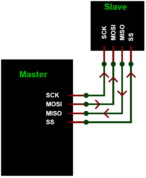
SPI has following four lines MISO, MOSI, SS, and CLK
- MISO (Master in Slave Out) - The Slave line for sending data to the master.
- MOSI (Master Out Slave In) - The Master line for sending data to the peripherals.
- SCK (Serial Clock) - The clock pulses which synchronize data transmission generated by the master.
- SS (Slave Select) –Master can use this pin to enable and disable specific devices.
SPI Master with Multiple Slaves
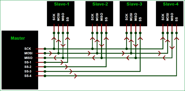
To start communication between master and slave we need to set the required device's Slave Select (SS) pin to LOW, so that it can communicate with the master. When it's high, it ignores the master. This allows you to have multiple SPI devices sharing the same MISO, MOSI, and CLK lines of master. As you can see in the above image there are four slaves in which the SCLK, MISO, MOSI are common connected to master and the SS of each slave is connected separately to individual SS pins (SS1, SS2, SS3) of master. By setting the required SS pin LOW a master can communicate with that slave.
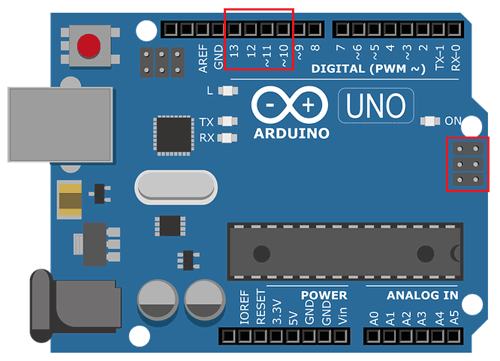
SPI Pins in Arduino UNO
The image below shows the SPI pins present Arduino UNO (in red box).
|
SPI Line |
Pin in Arduino |
|
MOSI |
11 or ICSP-4 |
|
MISO |
12 or ICSP-1 |
|
SCK |
13 or ICSP-3 |
|
SS |
10 |
Using SPI Protocol in Arduino
Before start programming for SPI communication between two Arduinos. We need to learn about the Arduino SPI library used in Arduino IDE.
The library <SPI.h> is included in the program for using the following functions for SPI communication.
1. SPI.begin()
USE: To Initialize the SPI bus by setting SCK, MOSI, and SS to outputs, pulling SCK and MOSI low, and SS high.
2. SPI.setClockDivider(divider)
USE: To Set the SPI clock divider relative to the system clock. The available dividers are 2, 4, 8, 16, 32, 64 or 128.
Dividers:
- SPI_CLOCK_DIV2
- SPI_CLOCK_DIV4
- SPI_CLOCK_DIV8
- SPI_CLOCK_DIV16
- SPI_CLOCK_DIV32
- SPI_CLOCK_DIV64
- SPI_CLOCK_DIV128
3. SPI.attachInterrupt(handler)
USE: This function is called when a slave device receives data from the master.
4. SPI.transfer(val)
USE: This function is used to simultaneous send and receive the data between master and slave.
So now let’s start with practical demonstration of SPI protocol in Arduino. In this tutorial we will use two arduino one as master and other as slave. Both Arduino are attached with a LED & a push button separately. Master LED can be controlled by using slave Arduino’s push button and slave Arduino’s LED can be controlled by master Arduino’s push button using SPI communication protocol present in arduino.
Components Required for Arduino SPI communication
- Arduino UNO (2)
- LED (2)
- Push Button (2)
- Resistor 10k (2)
- Resistor 2.2k (2)
- Breadboard
- Connecting Wires

Arduino SPI Communication Circuit Diagram
The below circuit diagram shows how to use SPI on Arduino UNO, but you can follow the same procedure for Arduino Mega SPI Communication or Arduino nano SPI communication. Almost everything will remain the same except for the pin number. You have to check the pinout of Arduino nano or mega to find the Arduino nano SPI pins and Arduino Mega pins, once you have done that everything else will be the same.

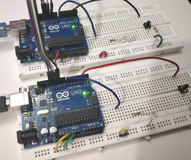
I have built the above-shown circuit over a breadboard, you can see the circuit set-up that I used for testing below.
How to Program Arduino for SPI Communication:
This tutorial has two programs one for master Arduino and other for slave Arduino. Complete programs for both sides are given at the end of this project.
Arduino SPI Master Programming Explanation
1. First of all we need to include the SPI library for using SPI communication functions.
#include<SPI.h>
2. In void setup()
- We Start Serial Communication at Baud Rate 115200.
Serial.begin(115200);
- Attach LED to pin 7 and Push button to pin 2 and set those pins OUTPUT and INPUT respectively.
pinMode(ipbutton,INPUT);
pinMode(LED,OUTPUT);
- Next we begin the SPI communication
SPI.begin();
- Next we set the Clockdivider for SPI communication. Here we have set divider 8.
SPI.setClockDivider(SPI_CLOCK_DIV8);
- Then set the SS pin HIGH since we didn’t start any transfer to slave arduino.
digitalWrite(SS,HIGH);
3. In void loop():
- We read the status of the pushbutton pin connected to pin2 (Master Arduino) for sending those value to the slave Arduino.
buttonvalue = digitalRead(ipbutton);
- Set Logic for Setting x value (To be sent to slave) depending upon input from pin 2
  if(buttonvalue == HIGH)
  {
    x = 1;
  }
  else
  {
    x = 0;
  }
- Before sending the value we need to LOW the slave select value to begin the transfer to slave from master.
digitalWrite(SS, LOW);
- Here comes the important step, in the following statement we send the push button value stored in Mastersend variable to the slave arduino and also receive value from slave that will be store in Mastereceive variable.
Mastereceive=SPI.transfer(Mastersend);
- After that depending upon the Mastereceive value we will turn the Master Arduino LED ON or OFF.
  if(Mastereceive == 1)
  {
    digitalWrite(LED,HIGH);        //Sets pin 7 HIGH
    Serial.println("Master LED ON");
  }
  else
  {
   digitalWrite(LED,LOW);         //Sets pin 7 LOW
   Serial.println("Master LED OFF");
  }
Note: We use serial.println() to view the result in Serial Motor of Arduino IDE. Check the Video at the end.
Arduino SPI Slave Programming Explanation
1. First of all we need to include the SPI library for using SPI communication functions.
#include<SPI.h>
2. In void setup()
- We Start Serial Communication at Baud Rate 115200.
Serial.begin(115200);
- Attach LED to pin 7 and Push button to pin2 and set those pins OUTPUT and INPUT respectively.
pinMode(ipbutton,INPUT);
pinMode(LED,OUTPUT);
- The important step here is the following statements
pinMode(MISO,OUTPUT);
The above statement sets MISO as OUTPUT (Have to Send data to Master IN). So data is sent via MISO of Slave Arduino.
- Now Turn on SPI in Slave Mode by using SPI Control Register
SPCR |= _BV(SPE);
- Then turn ON interrupt for SPI communication. If a data is received from master the Interrupt Routine is called and the received value is taken from SPDR (SPI data Register)
SPI.attachInterrupt();
- The value from master is taken from SPDR and stored in Slavereceived variable. This takes place in following Interrupt Routine function.
ISR (SPI_STC_vect)
{
  Slavereceived = SPDR;
  received = true;
}
3. Next in void loop () we set the Slave arduino LED to turn ON or OFF depending upon the Slavereceived value.
  if (Slavereceived==1)
   {
   digitalWrite(LEDpin,HIGH); //Sets pin 7 as HIGH LED ON
                                     Serial.println("Slave LED ON");
     }
else
      {
  digitalWrite(LEDpin,LOW);     //Sets pin 7 as LOW LED OFF
  Serial.println("Slave LED OFF");
      }
- Next we read the status of the Slave Arduino Push button and store the value in Slavesend to send the value to Master Arduino by giving value to SPDR register.
  buttonvalue = digitalRead(buttonpin);
  if (buttonvalue == HIGH)
      {
        x=1;
      }
else
      {
       x=0;
      }
            Slavesend=x;
            SPDR = Slavesend;
Note: We use serial.println() to view the result in Serial Motor of Arduino IDE. Check the Video at the end.
How does SPI work on Arduino? - Let's test it!
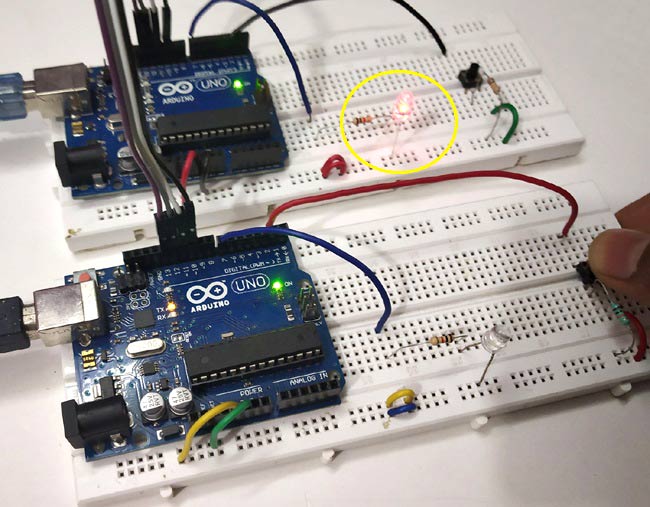
Below is the picture of final setup for SPI communication between two Arduino Boards.
When push button at Master side is pressed, white LED at slave side turns ON.
And when the push button at Slave side is pressed, Red LED at Master side turns ON.
You can check out the video below to see the demonstration of Arduino SPI communication. If you have any questions please leave them in the comment section our use our forums.
Complete Project Code
Master Arduino Code:

//SPI MASTER (ARDUINO)

//SPI COMMUNICATION BETWEEN TWO ARDUINO

//CIRCUIT DIGEST
#include<SPI.h>                             //Library for SPI

#define LED 7

#define ipbutton 2

int buttonvalue;

int x;

void setup (void)
{

  Serial.begin(115200);                   //Starts Serial Communication at Baud Rate 115200


  pinMode(ipbutton,INPUT);                //Sets pin 2 as input

  pinMode(LED,OUTPUT);                    //Sets pin 7 as Output


  SPI.begin();                            //Begins the SPI commnuication

  SPI.setClockDivider(SPI_CLOCK_DIV8);    //Sets clock for SPI communication at 8 (16/8=2Mhz)

  digitalWrite(SS,HIGH);                  // Setting SlaveSelect as HIGH (So master doesnt connnect with slave)

}
void loop(void)

{

  byte Mastersend,Mastereceive;
  buttonvalue = digitalRead(ipbutton);   //Reads the status of the pin 2
  if(buttonvalue == HIGH)                //Logic for Setting x value (To be sent to slave) depending upon input from pin 2

  {

    x = 1;

  }

  else

  {

    x = 0;

  }


  digitalWrite(SS, LOW);                  //Starts communication with Slave connected to master


  Mastersend = x;

  Mastereceive=SPI.transfer(Mastersend); //Send the mastersend value to slave also receives value from slave


  if(Mastereceive == 1)                   //Logic for setting the LED output depending upon value received from slave

  {

    digitalWrite(LED,HIGH);              //Sets pin 7 HIGH

    Serial.println("Master LED ON");

  }

  else

  {

   digitalWrite(LED,LOW);               //Sets pin 7 LOW

   Serial.println("Master LED OFF");

  }

  delay(1000);

}

Slave Arduino Code:

//SPI SLAVE (ARDUINO)

//SPI COMMUNICATION BETWEEN TWO ARDUINO

//CIRCUIT DIGEST

//Pramoth.T
#include<SPI.h>

#define LEDpin 7

#define buttonpin 2

volatile boolean received;

volatile byte Slavereceived,Slavesend;

int buttonvalue;

int x;

void setup()
{

  Serial.begin(115200);


  pinMode(buttonpin,INPUT);               // Setting pin 2 as INPUT

  pinMode(LEDpin,OUTPUT);                 // Setting pin 7 as OUTPUT

  pinMode(MISO,OUTPUT);                   //Sets MISO as OUTPUT (Have to Send data to Master IN
  SPCR |= _BV(SPE);                       //Turn on SPI in Slave Mode

  received = false;
  SPI.attachInterrupt();                  //Interuupt ON is set for SPI commnucation


}
ISR (SPI_STC_vect)                        //Inerrrput routine function

{

  Slavereceived = SPDR;         // Value received from master if store in variable slavereceived

  received = true;                        //Sets received as True

}
void loop()

{ if(received)                            //Logic to SET LED ON OR OFF depending upon the value recerived from master

   {

      if (Slavereceived==1)

      {

        digitalWrite(LEDpin,HIGH);         //Sets pin 7 as HIGH LED ON

        Serial.println("Slave LED ON");

      }else

      {

        digitalWrite(LEDpin,LOW);          //Sets pin 7 as LOW LED OFF

        Serial.println("Slave LED OFF");

      }


      buttonvalue = digitalRead(buttonpin);  // Reads the status of the pin 2


      if (buttonvalue == HIGH)               //Logic to set the value of x to send to master

      {

        x=1;


      }else

      {

        x=0;

      }


  Slavesend=x;

  SPDR = Slavesend;                           //Sends the x value to master via SPDR

  delay(1000);

}

}
Comments
For anyone confused by the…
For anyone confused by the resistors, follow the photo not the wiring diagram. That means use10kΩ resistors between the switch and earth / black rail, not 220Ω. It's not a catastrophic error, just allows a bit of excessive / unnecessary current while the button is pressed.
Excellent tutorial otherwise. Bookmarked.
A fun sketch. But I'm a bit…
A fun sketch. But I'm a bit puzzled as how this is intended to work.
- In the slave sketch the boolean "received" is set to true first time the ISR is executed and never set to false again.
- The slave if-block if(received) {} extends over the entire loop. Hence, the slave only reads and sends its own push button state if it has received data from the master.
- The master has no ISR. So the reaction to receiving data from the slave is delayed until the master loop again reaches the SPI.transfer statement.
As much as I can see (don't have two Arduinos) the slave is chosen to be subordinate compared to the master. While there need to be a master and a slave in the SPI protocol, it should be possible to make the two equal in terms of actions. But that would require the use of ISR on both, I think.

Hello, Great tutorial, I am going to mess with this a bit to see if it works for me. Question. I noticed the "Master" code uses pin10 as SS (Slave Select). My understand from this article is so that the slave knows wheter communication is bound for it or not. however in the code for the slave, I don't see the SS utilized. This would make me thing that the slave unit in this example would listen and respond to any and all communication on the SPI without regard to the masters SS. Is this correct? How would you correct this? in my use case I have multiple slave devices on my SPI bus.