
Today digital meters are replacing analog meters in every sector whether its electricity meter or taxi fare meter. The main reason for that is analog meters have mechanical parts that tend to wear when used for long time and they are not as accurate as digital Meters.
A good example for this is analog speedometer and odometer that is used in old motor bikes for measuring speed and distance travelled. They have a special parts called pinion and rack arrangement in which a cable is used to rotate speedometer’s pin when wheel is rotated. This will wear out when using for long period and also needs replacement and maintenance.
In digital meter, instead of using mechanical parts, some sensors like optical interrupter or hall sensor is used to calculate the speed and distance. This is more accurate than the analog meters and doesn’t require any maintenance for long period of time. We previously built many digital speedometer projects using different sensors:
- DIY Speedometer using Arduino and Processing Android App
- Digital Speedometer and Odometer Circuit using PIC Microcontroller
- Speed, Distance and Angle Measurement for Mobile Robots using LM393 Sensor (H206)
Today, in this tutorial we will make a prototype of a Digital Taxi Fare Meter using Arduino. This project calculates speed and distance travelled by the taxi’s wheel and continuously displays it on 16x2 LCD display. And based on distance travelled it generates fare amount when we press push button.
Below image shows the complete setup of Digital Taxi Meter Project
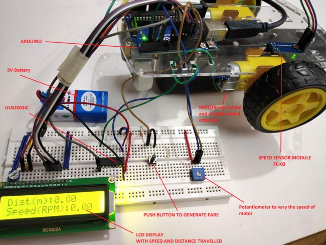
This prototype has a RC car chassis with a Speed sensor module and an encoder wheel attached to motor. Once speed is measured, we can measure the distance travelled and find the fare amount value by pressing push button. We can set the speed of the wheel using potentiometer. To learn more about using LM-393 Speed Sensor module with Arduino, follow the link. Let’s see a short introduction of Speed sensor module.
Infrared Slotted Optical LM-393 Speed Sensor Module
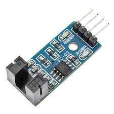
This is a slot type module that can be used for measuring speed of rotation of encoder wheels. This Speed sensor module works based on slot type optical interrupter also known as optical source sensor. This module requires a voltage of 3.3V to 5V and produces digital output. So it can be interfaced with any microcontroller.
The Infrared Light sensor consists consists of light source (IR-LED) and a phototransistor sensor. Both are placed with a small gap in-between them. When an object is placed in between the gap of IR LED and phototransistor it will interrupt the light beam causing phototransistor to stop passing current.
Thus with this sensor a slotted disc (Encoder Wheel) is used that can be attached to a motor and when the wheel rotates with motor it interrupts the light beam between IR LED and phototransistor that makes output On and Off (Creating Pulses).
Thus it produces HIGH output when there is interrupt between source and sensor (When any object is placed in between) and produces LOW output when there is no object placed. In the module we have an LED to indicated the optical interrupt caused.
This module comes with LM393 Comparator IC which is used to produce accurate HIGH and LOW signals at the OUTPUT. Thus this module is sometimes called as LM393 Speed sensor.
Measuring Speed and Distance Travelled to Calculate Fare
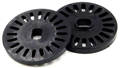
To measure the speed of rotation we need to know the number of slots present in encoder wheel. I have an encoder wheel with 20 slots in it. When they rotate one complete rotation we have 20 pulses at the output. So to calculate speed we need number of pulses produced per second.
For example
If there are 40 pulses in one second, then
Speed = Noo. Of pulses / No. of slots = 40/20 = 2RPS (Revolution per second)
For calculating speed in RPM (Revolutions per Minute) multiply with 60.
Speed in RPM = 2 X 60 = 120 RPM (Revolutions per Minute)
Measuring Distance
Measuring distance travelled by the wheel is so simple. Before calculating distance, the circumference of the wheel should be known.
Circumference of the wheel = π*d
Where d is the diameter of the wheel.
Value of π is 3.14.
I have a wheel (RC car wheel) of diameter 6.60 cm so the circumference is (20.7 cm).
So to calculate the distance travelled, just multiply the no of pulses detected with the circumference.
Distance Travelled = Circumference of Wheel x (No. of Pulses / No. of slots)
So when a wheel of Circumference 20.7cm takes 20 pulses that is one rotation of encoder wheel then the distance travelled by wheel is calculated by
Distance travelled = 20.7 x (20/20) = 20.7cm
In order to calculate the distance in meter divide the distance in cm value by 100.
Note: This is a small RC car wheel, in real time cars have bigger wheels than this. So I’m assuming that circumference of the wheel to be 230cm in this tutorial.
Calculating the Fare Based on Distance Travelled
To get the total fare amount, multiply the distance travelled with the fare rate (amount/meter).
Note: In this tutorial I’m assuming that Rs 5 is charged per meter.
So if the wheel is travelled 20m then fare amount will be 20*5=100 rupees.
So now let’s get the components and build the circuit.
Components Required
- Arduino UNO
- LCD (16x2)
- Push Button
- Potentiometer -10k
- ULN2003 Motor Driver IC
- LM393 Speed Sensor Module (FC-03)
- RC Smart Car Chassis with Speed encoder
- Battery 9V
- Breadboard
- Connecting Wires
Circuit Diagram
Circuit diagram for Digital Taxi Fare Meter Project using Arduino is given below:

Mounting Speed Sensor with RC Car Chassis
Speed sensor is mounted with the encoder wheel present in between the gap of sensor. In my chassis I have a special hole for placing the sensor. See the image below


Connections between Speed sensor module and Arduino
|
SPEED SENSOR (FC-03) |
ARDUINO |
|
VCC |
5V |
|
GND |
GND |
|
D0 |
2 |
Connection between Arduino & 16x2 LCD
|
LCD |
ARDUINO |
|
VSS |
GND |
|
VDD |
+5V |
|
V0 |
From potentiometer output for contrast of LCD |
|
RS |
12 |
|
RW |
GND |
|
EN |
13 |
|
D4 |
8 |
|
D5 |
9 |
|
D6 |
10 |
|
D7 |
11 |
|
A |
+5V |
|
K |
GND |
Learn more about interfacing LCD with Arduino here.
Connection between Arduino & ULN2003
|
ARDUINO |
ULN2003 |
|
5 |
IN1 |
|
GND |
GND |
Connection between ULN2003, DC Motor and 9v Battery
I have used a 9V battery and ULN2003 IC to externally power the motor.
|
ULN2003 |
MOTOR |
9V battery |
|
OUT1 |
-Ve Motor |
- |
|
COM |
+Ve Motor |
+Ve |
|
GND |
- |
-Ve |
Push button & Potentiometer Connection
A push button with pull down resistor is connected to the pin 3 of Arduino for generating fare amount when pressed.
A potentiometer is used to give analog input voltage to the pin A0 of the Arduino for varying speed of the motor wheel.
Programming Arduino for Digital Taxi Meter
Complete code with a demonstration Video is given at the end of this tutorial. Here we understand few important parts of the code.
Before getting into the code we need to know about interrupts and timer One library as they are used in the code.
Interrupts is used here because we need to constantly check the output detected at the speed sensor module as the high priority. So ISR is used in the code. ISR is interrupt service routine that is called when an interrupt is occurred at the interrupt pins 2 & 3.
Arduino UNO has two interrupt pins 2 and 3.
At pin 2, output from D0 of speed sensor is connected.
At pin 3, a push button with pulldown resistor is connected.
TimerOne library is used in this code to check how many rotations (how many pulses) are detected for one second and from that we can calculate the speed per second and display them at the output. This ISR function executes for every second
So let’s see our code in detail:
1. First of all, include libraries for the functions are going to be used in programme.
#include "TimerOne.h"
#include <LiquidCrystal.h>
2. Next declare the global variables as they will be used throughout the program.
volatile unsigned int counter=0;
volatile unsigned int rotation=0;
float rotationinm=0;
unsigned int speed=0;
3. Next define and initialize the LCD pins that are connected to Arduino.
const int rs = 12, en = 13, d4 = 8, d5 = 9, d6 = 10, d7 = 11;
LiquidCrystal lcd(rs, en, d4, d5, d6, d7);
4. Next in the void setup()
Define the pin mode, here PIN A0 is used for taking Analog input from potentiometer and pin 5 to write analog output which is connected to IN1 pin of ULN2003 IC.
pinMode(A0,INPUT);
pinMode(5,OUTPUT);
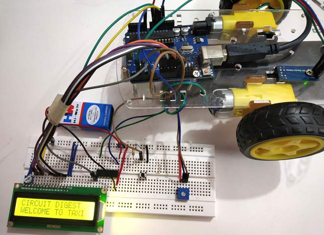
Next display some welcome message and clear them.
  lcd.begin(16,2);                   //Sets LCD as 16x2 type
  lcd.setCursor(0,0);
  lcd.print("CIRCUIT DIGEST");
  lcd.setCursor(0,1);
  lcd.print("WELCOME TO TAXI");
  delay(3000);
  lcd.clear();
  lcd.print("LETS START :)");
  delay(1000);
  lcd.clear();
Next important part is to set the Interrupt pin and the ISR to be called when interrupt happens
First we need to set timer1 for 1 second and next attach an ISR for timer1 so that this ISR is called every second. The ISR name is timerIsr
Timer1.initialize(1000000);
Timer1.attachInterrupt( timerIsr );
Next attach two external interrupts. First interrupt makes the Arduino pin 2 as interrupt pin and calls ISR (count) when there is RISING (LOW TO HIGH) detected at the pin 2. This pin 2 is connected to the D0 output of the speed sensor module.
And second one makes the Arduino pin 3 as interrupt pin and calls ISR (generatefare) when HIGH is detected at the pin3. This pin is connected to the push button with a pull down resistor.
attachInterrupt(digitalPinToInterrupt(2), count, RISING);
attachInterrupt(digitalPinToInterrupt(3), generatefare, HIGH);
5. Next let’s see about the ISR we used here:
ISR1- count() ISR is called when an RISING (LOW TO HIGH) is happened at the pin 2 (connected to speed sensor).
void count()  // ISR for counts from the speed sensor
{
  counter++;  // increase the counter value by one
  rotation++; //Increase the rotation value by one
  delay(10);
}
ISR2- timerIsr() ISR is called every one second and execute those lines present inside the ISR.
void timerIsr()
{
 detachInterrupt(digitalPinToInterrupt(2));
 Timer1.detachInterrupt();
 lcd.clear();

 float speed = (counter / 20.0)* 60.0;
 float rotations = 230*( rotation / 20);
 rotationinm = rotations/100;

 lcd.setCursor(0,0);
 lcd.print("Dist(m):");
 lcd.print(rotationinm);
 lcd.setCursor(0,1);
 lcd.print("Speed(RPM):");
 lcd.print(speed);
  counter=0;

  int analogip = analogRead(A0);
  int motorspeed = map(analogip,0,1023,0,255);
  analogWrite(5,motorspeed);

 Timer1.attachInterrupt( timerIsr );
 attachInterrupt(digitalPinToInterrupt(2), count, RISING);
}
This function contains the lines that actually first detach the Timer1 and Interrupt pin2 first because we have LCD print statements inside the ISR.
For calculating SPEED in RPM we use below code where 20.0 is the no of slots preset in the encoder wheel.
float speed = (counter / 20.0) * 60.0;
And for calculating distance below code is used:
float rotations = 230*( rotation / 20);
Here the circumference of wheel is assumed as 230cm (as this is normal for real time cars)
Next convert the distance in m by dividing the distance by 100
rotationinm = rotations/100;
After that we display the SPEED and DISTANCE on LCD display
 lcd.setCursor(0,0);
 lcd.print("Dist(m):");
 lcd.print(rotationinm);
 lcd.setCursor(0,1);
 lcd.print("Speed(RPM):");
 lcd.print(speed);
IMPORTANT: We have to reset the counter to 0 because we need to get number of pluses detected for per second so we use this line
counter=0;
Next read the analog pin A0 and convert it into digital value (0 to 1023) and further map those values to 0-255 for PWM output (Setting speed of motor) and finally write those PWM values using analogWrite function that is connected to the ULN2003 Motor IC.
int analogip = analogRead(A0);
 int motorspeed = map(analogip,0,1023,0,255);
 analogWrite(5,motorspeed);
ISR3: generatefare() ISR is used to generate the fare amount based on the distance travelled. This ISR is called when interrupt pin 3 is detected HIGH (When push button pressed). This function detaches the interrupt at pin 2 and the timer interrupt and then clears the LCD.
void generatefare()
{
   detachInterrupt(digitalPinToInterrupt(2)); pin at 2
   Timer1.detachInterrupt();
   lcd.clear();
   lcd.setCursor(0,0);
   lcd.print("FARE Rs: ");
   float rupees = rotationinm*5;
   lcd.print(rupees);
   lcd.setCursor(0,1);
   lcd.print("Rs 5 per metre");
   }
After that distance travelled is multiplied with 5 (I have used 5 for the rate INR 5/meter). You can change according to your wish.
float rupees = rotationinm*5;
After calculating the amount value display it on the LCD display connected to Arduino.
   lcd.setCursor(0,0);
   lcd.print("FARE Rs: ");
   lcd.print(rupees);
   lcd.setCursor(0,1);
   lcd.print("Rs 5 per metre");
Complete code and demonstration Video is given below.
You can further improve this prototype by increasing accuracy, robustness and adding more features like android app, digital payment etc and develop it as a product.
Complete Project Code
#include "TimerOne.h"                      //Include Timer1 library for using Timer1 functions

#include <LiquidCrystal.h>                 //Include LCD library for using LCD display functions
const int rs = 12, en = 13, d4 = 8, d5 = 9, d6 = 10, d7 = 11;   //Define the LCD pins

LiquidCrystal lcd(rs, en, d4, d5, d6, d7);
volatile unsigned int counter=0;

volatile unsigned int rotation=0;

float rotationinm=0;

unsigned int speed=0;
void count()  // ISR for counts from the speed sensor

{

  counter++;  //increase the counter value by one

  rotation++; //Increase the rotation value by one

  delay(10);

}
void timerIsr()

{

 detachInterrupt(digitalPinToInterrupt(2));          //Stops the interrupt pin 2

 Timer1.detachInterrupt();                           //Stops the timer1 interrupt
 lcd.clear();


 float speed = (counter / 20.0)* 60.0;              //Calcukate speed in minute (20-No of slots in Encoder Wheel)

 float rotations = 230*( rotation / 20);            //Calculate distance in cm (230-Circumference of the wheel assumed 20- No of slots)

 rotationinm = rotations/100;
 lcd.setCursor(0,0);

 lcd.print("Dist(m):");

 lcd.print(rotationinm);                            //Display rotationinm at LCD

 lcd.setCursor(0,1);

 lcd.print("Speed(RPM):");

 lcd.print(speed);                                  //Dsiplay speed in RPM


  counter=0;                                        //Reset counter to 0
  int analogip = analogRead(A0);                   // Analog read from pin A0

  int motorspeed = map(analogip,0,1023,0,255);     //convert digital vales 0-1023 to 0-255

  analogWrite(5,motorspeed);                      //Sets PWM value at pin 5


 Timer1.attachInterrupt( timerIsr );                        //Starts timer1 again

 attachInterrupt(digitalPinToInterrupt(2), count, RISING);  //Attaches interrupt at pin2 again

}
void generatefare()                           //ISR to generate the fareamount

{

   detachInterrupt(digitalPinToInterrupt(2)); //Disables the Interrupt pin at 2

   Timer1.detachInterrupt();                  //Disables the Timer1 interrupt

   float rupees = rotationinm*5;              //Muliply 5 with distance travelled (Rs 5 per meter )

   lcd.clear();                               //Clears LCD

   lcd.setCursor(0,0);

   lcd.print("FARE Rs: ");

   lcd.print(rupees);                        //Display fare amount

   lcd.setCursor(0,1);

   lcd.print("Rs 5 per metre");

}
void setup()

{

  pinMode(A0,INPUT);                 //Sets pin A0 as INPUT

  pinMode(5,OUTPUT);                 //Sets pin 5 as OUTPUT


  lcd.begin(16,2);                   //Sets LCD as 16x2 type

  lcd.setCursor(0,0);                //The following code displays welcome messages

  lcd.print("CIRCUIT DIGEST");

  lcd.setCursor(0,1);

  lcd.print("WELCOME TO TAXI");

  delay(3000);

  lcd.clear();

  lcd.print("LETS START :)");

  delay(1000);

  lcd.clear();
  Timer1.initialize(1000000);          //Initilize timer1 for 1 second

  Timer1.attachInterrupt( timerIsr );  //ISR routine to be called for every one second


  attachInterrupt(digitalPinToInterrupt(2), count, RISING);     // Pin 2 as Interrupt pin with count ISR is called when LOW to RIGH happens.

  attachInterrupt(digitalPinToInterrupt(3), generatefare, HIGH); //Pin 3 as Interrupt pin with generatefare ISR is called when HIGH is detected.

 }
void loop()

{


}
Comments
Hey Scott, LCD with I2C pinout can be easily interfaced with Arduino. Infact it is easier to connect them to Arduino than the converntional methond.
Hey Scott, LCD with I2C pinout can be easily interfaced with Arduino. Infact it is easier to connect them to Arduino than the converntional methond.
what is the circular thing near the lcd? (upper left)
It's a potentiometer, for varying the contrast of the LCD display
I built it but its not working
Can we please have a meeting to fix this I have to get it done by next week for university submission
my email - itseditortime@outlook.com
i connect this project but LCD not displaying anything please help me
Hello, Sir, I tried to connect but it is not working according to the speed sensor.can you help me

I have a LCD that uses a I2C connection (four pins, (GND, VCC, SDA, SCL). Is there any way to complete this project using these four pins and connections? If so would love code and if this is possible. Thank you