
Door alarm is a very common and useful device for security purpose. They are used to detect whether the Door is open or closed. Often we have seen some door alarm in the refrigerator that produced a different sound when they activate. Door Alarm Projects are very popular among the Electronics students and hobbyists. We have also built many alarms based on various technologies:
- Door Alarm using Arduino and Ultrasonic Sensor
- Laser Security Alarm Circuit
- IR Based Security Alarm
- Burglar Alarm using PIR
- GSM Based Security System
This time we have decided to make a Door Alarm by using Hall Effect Sensor and 555 timer IC.
Components Required:
- 555 Timer IC
- Buzzer
- Bread Board
- Resistor 1K -4
- Resistor 10K
- 50k POT
- LED
- 10uF Capacitor
- Jumper wire
- 9V battery or supply
- LM7805 Voltage Regulator
- Transistor BC547
- 3144 Hall Effect Magnet Sensor
Hall Effect Sensor:
A Hall sensor is a device which can detect the presence of a magnet based on its polarity. It is a transducer which generates a signal according to magnetic field present near it. Here we have used 3144 Hall Effect Sensor which has a range of about 2cm.
As the name suggests the Hall Effect sensor works with the principle of “Hall effect”. According to this law “when a conductor or semiconductor with current flowing in one direction was introduced perpendicular to a magnetic field a voltage could be measured at right angles to the current path”. Using this technique, the hall sensor will be able to detect the presence of magnet around it. We have previously Interfaced Hall sensor with Arduino and made few projects using Hall sensor.


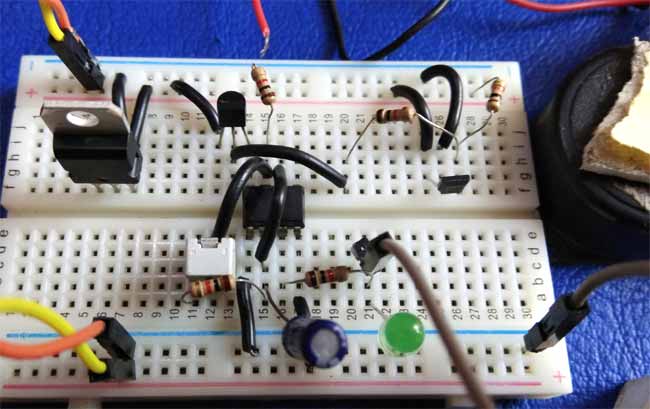
Circuit Diagram and Explanation:

In this Magnetic Door Alarm circuit, we have used a 555 timer IC in astable mode to generate a tone as an alarm; frequency of tone can be adjustable by using an attached RV1 potentiometer. Here we have connected a 1k (R1) resistor between Vcc and pin 7th of 555 Timer (U2) and a 1k (R4) resistor & 50k Pot (RV1) between pin 7 and 6. Pin 2 shorted with pin 6 and a 10uf C1 capacitor is connected to pin 2 with respect to ground. Pin 1 is connected to ground and pin 4 directly connected to VCC and pin 8 as well by using a transistor. A Hall Effect Sensor or magnet sensor is used to detect if the door is open and close. It's output connected to the base of the transistor BC547 which is responsible to provide a path to 555 timer IC. A buzzer and an LED are connected on Pin 3 of 555 for indication of alarm. Finally, we have connected a 9v Battery to power the circuit.
Working Explanation:
Working on this Magnetic Door Alarm is tricky. Here we have made a 555 astable multi-vibrator for generating alarm signal as we already mentioned. But we are controlling this astable multi-vibrator U2 by using Hall Sensor U3 through an NPN transistor Q1 BC547.
When we put magnate near Hall Sensor then hall sensor senses the magnetic field and generates a Low signal as an output. This output goes to the base of the transistor. Due to Low signal, transistor remains turned off and power is not supplied to 555 timer IC and buzzer remains silent with LED turned off.
Now when we take magnate far from the hall sensor then hall sensor generates a High signal which goes to the base of the transistor. Due to high signal transistor gets turned on and make a path for astable multi-vibrator supply. And when astable multi-vibrator has supply then it starts working and generates an alarm tone and flashing LED as well. The user can change the frequency of tone by moving RV1 potentiometer.
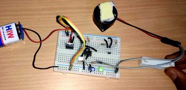
So now we can attach this circuit in Door frame and a magnet in the Door, now when the gate is closed magnet (door) and hall sensor (Door Frame) will remain near and the alarm will remain off. Whenever someone opens the door, the magnet will get away from the Hall sensor and it will make the hall sensor High and trigger the LED and alarm connected to 555 IC.
Comments
Swapping of transistor
Can we use BC546 instead of BC547 transistor?
is there no need to put
is there no need to put capacitors in the input and output of LM7805?
It will work even without the
It will work even without the capacitor, but yes using it is recommended
Not working
When I am making the circuit, the circuit is not working


It's okay to me