

Sensors have always been a vital component in any Project. These are the ones which convert the real real-time environmental data into digital/variable data so that it can be processed by electronics. There are many different types of sensors available in the market and you can select one based on your requirements. In this project we will learn how to use a Hall sensor a.k.a Hall effect sensor with Arduino. This sensor is capable of detecting a magnet and also the pole of the magnet.
Why detect a magnet?, You may ask. Well there are a lot of applications which practically use Hall Effect sensor and we might have never noticed them. One common application of this sensor is to measure speed in bicycles or any rotating machines. This sensor is also used in BLDC motors to sense the position of Rotor Magnets and trigger the Stator coils accordingly. The applications are endless, so let’s learn how to Interface Hall effect sensor Arduino to add up another tool in our arsenal. Here are some projects with Hall sensor:
- DIY Speedometer using Arduino and Processing Android App
- Digital Speedometer and Odometer Circuit using PIC Microcontroller
- Virtual Reality using Arduino and Processing
- Magnetic Field Strength Measurement using Arduino
In this tutorial we will use interrupts function of Arduino to detect the magnet near Hall sensor and glow a LED. Most of the time Hall sensor will be used only with Interrupts because of their applications in which high reading and executing speed is required, hence let us also use interrupts in our tutorial.
Materials Required:
- Hall Effect Sensor (A3144, or any other digital version)
- Arduino (Any version)
- 10k ohm and 1K ohm Resistor
- LED
- Connecting Wires
Hall Effect Sensors:
Before we dive into the connections there are few important things that you should know about Hall Effect sensors. There are actually, two different types of Hall sensors one is Digital Hall sensor and the other is Analog Hall sensor. The digital Hall sensor can only detect if a magnet is present or not (0 or 1) but an analog hall sensor’s output varies based on the magnetic field around the magnet that is it can detect how strong or how far the magnet is. In this project will aim only at the digital Hall sensors for they are the most commonly used ones.
As the name suggests the Hall Effect sensor works with the principle of “Hall effect”. According to this law “when a conductor or semiconductor with current flowing in one direction was introduced perpendicular to a magnetic field a voltage could be measured at right angles to the current path”. Using this technique, the hall sensor will be able to detect the presence of magnet around it. Enough of theory let’s get into hardware.
Arduino Hall Effect Sensor Circuit Connections and Explanation:
The complete circuit diagram for interfacing Hall sensor with Arduino can be found below.

As you can see, the hall effect sensor arduino circuit diagram is pretty simple. But, the place where we commonly make mistakes is at figuring out the pin numbers of hall sensors. Place the readings facing you and the first pin on your left is the Vcc and then Ground and Signal respectively.
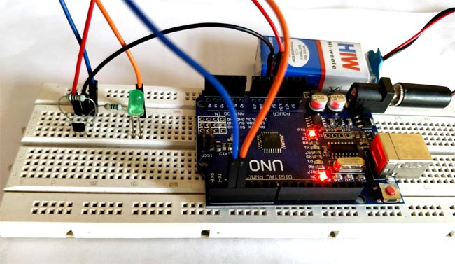
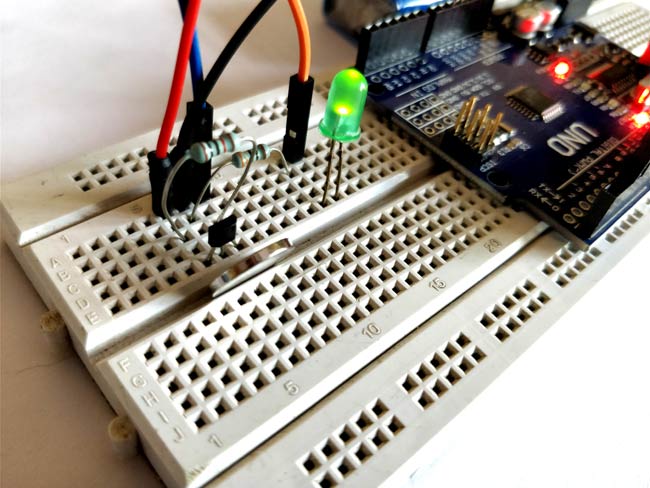
We are going to use Interrupts as told earlier, hence the output pin of Hall sensor is connected to the Pin 2 of the Arduino. The Pin is connected to a LED which will be turned ON when a magnet is detected. I have simply made the connections on a breadboard and it looked somewhat like this below once completed.
Arduino Hall Effect Sensor Code:
The complete Arduino code is just few lines and it can be found at the bottom of this page which can be directly uploaded to your Arduino Board. If you want to know how the program works read further.
We have one input, which is the sensor and one output which is a LED. The sensor has to be connected as an interrupt input. So inside our setup function, we initialize these pins and also make the Pin 2 to work as an interrupt. Here pin 2 is called Hall_sensor and pin 3 is called LED.
void setup() {
  pinMode(LED, OUTPUT); //LED is a output pin
  pinMode(Hall_sensor, INPUT_PULLUP); //Hall sensor is input pin
  attachInterrupt(digitalPinToInterrupt(Hall_sensor), toggle, CHANGE); //Pin two is interrupt pin which will call toggle function
}
When there is a interrupt detected, the toggle function will be called as mentioned in the above line. There are many interrupt parameters like Toggle, Change, Rise, Fall etc. but in this tutorial we are detecting the change of output from Hall sensor.
Now inside the toggle function, we use a variable called “state” which will just change its state to 0 if already 1 and to 1 if already zero. This way we can make the LED turn ON or Turn OFF.
void toggle() {
  state = !state;
}
Finally inside our loop function, we just have to control the LED. The variable state will be altered each time a magnet is detected hence we use it to determine if the LED should stay on or off.
void loop() {
  digitalWrite(LED, state);
}
Arduino Hall Effect Sensor Working:
Once you are ready with your Hardware and Code, just upload the Code to the Arduino. I have used a 9V battery to power the whole set-up you can use any preferable power source. Now bring the magnet close to the sensor and your LED will glow and if you take it away it will turn off.
Note: Hall sensor is Pole sensitive, meaning one side of the sensor can either detect only North Pole or only South Pole and not both. So if you bring a south pole close to the north sensing surface your LED will not glow.
What actually happens inside is, when we bring the magnet close to sensor the sensor changes its state. This change is sensed by the interrupt pin which will call the toggle function inside which we change the variable “state” from 0 to 1. Hence the LED will turn on. Now, when we move the magnet away from the sensor, again the output of sensor will change. This change is again noticed by our interrupt statement and hence the variable “state” will be changed from 1 to 0. Thus the LED if Turned off. The same repeats every time you bring a magnet close to the sensor.
The complete working video of the Arduino hall effect sensor project can be found below. Hope you understood the project and enjoyed building something new. If otherwise kindly use the comment section below or the forums for help.
Complete Project Code
const byte ledPin = 13;

const byte interruptPin = 2;

volatile byte state = LOW;

int val=0;
void setup() {

  pinMode(ledPin, OUTPUT);

  pinMode(interruptPin, INPUT_PULLUP);

  attachInterrupt(digitalPinToInterrupt(interruptPin), test, CHANGE);

  Serial.begin(9600);

}
void loop() {

  digitalWrite(ledPin, state);

  Serial.println(val/2);

}
void test() {

  state = !state;

  val++;

}
Comments
The pinout in your diagram and paragraph is wrong. Pin 1 is Vcc, pin 2 is GND, pin output

Good works, thanks.