
Line follower robot is one of the popular robotics projects among students and beginners because of its simplicity. It follows a line, either black or white, depending on how you program your microcontroller. Here we make a line follower robot using MSP430 launchpad from Texas Instruments, which follows the black line. If you are new to MSP430 launchpad, please read our Getting stared with MSP430 Tutorial.
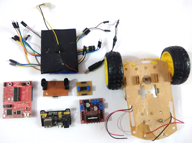
Materials Required
- MSP430G2 LaunchPad from Texas Instruments
- The L298D motor driver module
- Connecting wires
- IR sensor Modules
- Chasis, wheel, roller coaster
- Energia IDE
- Power supply (3.3v) and 5v-12v
Concepts of Line Follower
Concept of line follower is related to light. We have used the behaviour of light at black and white surface. When light fall on a white surface it will almost full reflects and in case of black surface light is absorbed by black surface. This explained behaviour of light is used in this line follower robot.

In this MSP430 based line follower robot we have used IR Transmitters and IR receivers also called photo diodes. They are used for sending and receiving light. IR transmits infrared lights. When infrared rays falls on white surface, it’s reflected back and caught by photodiodes which generates some voltage changes. When IR light falls on a black surface, light is absorb by the black surface and no rays are reflected back, thus photo diode does not receive any light or rays. To Learn more about IR sensors, follow the link.
Here in this MSP430 based line follower robot when sensor senses white surface then MSP gets 1 as input and when senses black line MSP gets 0 as input.
Circuit Explanation
We can divide the whole line follower robot into various sections like sensor section, control section and driver section.
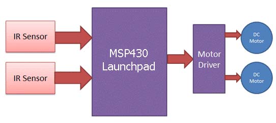
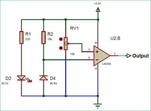
Sensor section: This section contains IR diodes, potentiometer, Comparator (Op-Amp) and LED’s. Potentiometer is used for setting reference voltage at comparator’s one terminal and IR sensors sense the line and provide a change in voltage at comparator’s second terminal. Then comparator compares both voltages and generates a digital signal at output. Here in this circuit we used two comparator for two sensors. LM358 is used as comparator. LM358 has inbuilt two low noise Op-amp.
Control Section: MSP430 Launchpad is used for controlling the whole process of line follower robot. The outputs of comparators are connected to digital pin P1_3 and P1_4 of MPS430 Launchpad. MSP430 Launchpad reads these signals and send commands to driver circuit to drive line follower.
Driver section: Driver section consists motor driver and two DC motors. Motor driver is used for driving motors because MSP430 Launchpad does not supply enough voltage and current to motor. So we added a motor driver circuit to get enough voltage and current for motor. Here we have used the L298d driver for driving DC Motors. MSP430 Launchpad sends commands to this motor driver and then it drives motors.
We have developed Line Follower Robots using different Micrcontroller:
- Line Follower Robot using 8051 Microcontroller
- Line Follower Robot using Arduino
- Line Follower Robot using Raspberry Pi
- Line Follower Robot using PIC Microcontroller
Working of Line Follower Robot using MSP430
Working of line follower is very interesting. Line follower robot senses black line by using sensor and then sends the signal to MSP430 Launchpad. Then MSP430 Launchpad drives the motor according to sensors' output.
Here in this project we are using two IR sensor modules namely left sensor and right sensor. When both left and right sensor senses white then robot move forward.
If left sensor comes on black line then robot turn left side.
If right sensor sense black line then robot turn right side until both sensor comes at white surface. When white surface comes robot starts moving on forward again.
If both sensors comes on black line, robot stops.

Circuit Diagram
Circuit for this MSP430 Line Follower Robot is very simple. The output of comparators is directly connected to MSP430 Launchpad’s digital pin number p1_3 and P1_4. And motor driver’s input pin IN1, IN2, IN3 and IN4 are connected at MSP430 Launchpad’s digital pin P1_5, P2_0, P2_1, P2_2 respectively. One motor is connected at the output pin of motor driver OUT1 and OUT2, and another motor is connected at OUT3 and OUT4. Here we have used 3.3v supply for power the whole circuit except Motor Driver module. We have supplied 8v to Motor driver module. The user can use 5v-12v.


You can also build your own IR module, like I built on Perf Board. Below is the circuit for IR Module:
Programming Explanation
Complete Program and Video can be found at the end of this Article.
In a program, first of all, we define the input and output pin for sensor and motors. Then define some macros for the direction of line follower and then write a directive to select sensor output
Note: Sensor may be active low or active high so first check what is the output of sensor then select directive by commenting or uncommenting activeLowMode. For active HIGH, comment the activeLowMode macro.
#define l_sensor P1_3
#define r_sensor P1_4

int pins[4]={P1_5,P2_0,P2_1,P2_2};

#define forward 0x05
#define left 0x06
#define right 0x09
#define stop 0x00

//#define activeLowMode

#ifdef activeLowMode
int res[4]={forward,left,right,stop};
#else
int res[4]={stop,right,left,forward};
#endif
After that, in setup function, we give direction to sensor and motor pin. And then in the loop function, we check inputs and send output to motor driver module to run the motors.
void setup()
{
  for(int i=0;i<4;i++)
  pinMode(pins[i], OUTPUT);
  pinMode(l_sensor, INPUT);
  pinMode(r_sensor, INPUT);
}

void loop()
{
  int sense=(digitalRead(l_sensor)<<1) | digitalRead(r_sensor);
  for(int i=0;i<4;i++)
    digitalWrite(pins[i], (res[sense]>>i) & 0x01);
}
There are four conditions in this line follower that we read by using MSP430 Launchpad. We have used two sensors namely the left sensor and the right sensor.
Conditions: Active HIGH output
|
Input |
Output |
Movement Of Robot |
||||
|
Left Sensor |
Right Sensor |
Left Motor |
Right Motor |
|||
|
LS |
RS |
LM1 |
LM2 |
RM1 |
RM2 |
|
|
0 |
0 |
0 |
0 |
0 |
0 |
Stop |
|
0 |
1 |
1 |
0 |
0 |
0 |
Turn Right |
|
1 |
0 |
0 |
0 |
1 |
0 |
Turn Left |
|
1 |
1 |
1 |
0 |
1 |
0 |
Forward |
Program is written according to the above table conditions. Check the complete Code and Demonstration Video below.
Complete Project Code
#define l_sensor P1_3

#define r_sensor P1_4
int pins[4]={P1_5,P2_0,P2_1,P2_2};
#define forward 0x05

#define left 0x06

#define right 0x09

#define stop 0x00
//#define activeLowMode
#ifdef activeLowMode

int res[4]={forward,left,right,stop};

#else

int res[4]={stop,right,left,forward};

#endif
void setup()

{

  for(int i=0;i<4;i++)

  pinMode(pins[i], OUTPUT);

  pinMode(l_sensor, INPUT);

  pinMode(r_sensor, INPUT);

}
void loop()

{

  int sense=(digitalRead(l_sensor)<<1) | digitalRead(r_sensor);

  for(int i=0;i<4;i++)

    digitalWrite(pins[i], (res[sense]>>i) & 0x01);

}

i want to built this home project pls help me with it