
In this project, we are going to Control the Speed of Dc Motor Wirelessly Using IR or TV Remote Control. Here we are not going to use any microcontroller. We have used basic components along with 555 Timer IC to complete this task. This circuit can control the DC motor speed in 5 different levels and any IR remote like TV/DVD remote etc can be used to control it.
Required Components:
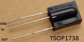
- TSOP1738 -1No.
- 555 timer IC -2Nos
- CD4017 -1No.
- BC547 Transistor -1No.
- 12-0-12 Transformer -1No.
- 1n4007 Diode -10Nos.
- Capacitor 1000uF, 1uF, 4.7uF, 0.01uF - 1No. each
- 0.1uF Cap -4Nos.
- Resistor 10k -2Nos
- Resistor 1k -3No.
- 220K Resistor 220k, 30k, 22k, 15k, 3.3k, 220, 650ohm -1No. each
- 330 Ohm Resistor 330ohm -3Nos.
- LEDs
Circuit Diagram and Working:

The Motor Speed Control Circuit is a little bit complex for beginners but overall it's easy. In this, we have TSOP1738 IR receiver U1 which is responsible for detecting the TV remote IR signal. Once it gets a signal from TV remote, it will trigger the 555 monostable Multivibrator U2. This Multivibrator is used for generating a single pulse every time when we press any of buttons on the IR remote control.
Generally TV IR remote sends 38KHz modulated pulses and TSOP1738 detects the IR radiation modulated at 38Khz. TSOP’s output is active low, means its output is remains HIGH when there is no IR, and becomes low when it detects IR radiation. It has three pins, Ground, Vs (power), and OUTPUT PIN. So whenever we press any button on IR remote, it triggers the Monostable 555 Timer (U2) by sending Low pulse to its Trigger PIN 2.
Further 555 Timer sends the clock pulse to Decade counter IC 4017 to shift its output to the next output pin. 4017 decade counter IC is used for changing the value of Timing Resistor for second 555 Timer IC (U4), which in configured in Astable Multivibrator Mode. This 555 IC is used for generating PWM Signal. Decade counter 4017 sets the resistance across the U4 Astable Multivibrator by switching its output to next output pin. And by changing the value of this Timing Resistor, duty cycle of PWM signal changes and hence the Speed of DC Motor changes each time we press the IR remote Button.
4017 IC is a CMOS decade counter chip. It can produce output at the 10 pins (Q0 – Q9) sequentially, means it produce output one by one at the 10 output pins. This output is shifted to pins through a LOW to HIGH clock pulse at PIN 14 (positive edge triggering). At first, output at Q0 (PIN 3) is HIGH, then with each clock pulse, output advance to the next PIN. Like one clock pulse makes the Q0 LOW and Q1 HIGH, and then the next clock pulse makes the Q1 LOW and Q2 HIGH, and so on. After the Q9, it will start from the Q0 again. To learn more about IC 4017 check our 4017 Circuits.

There are five selective resistance (R5, R6, R7, R8,R11) which are responsible to generate five different PWMs at the output pin of 555 IC (U4). In this circuit we have used 12v DC power supply for whole circuit. Here we have put a 4.7v zener diode to protect TSOP1738. The DC motor used here is a 12v DC Geared motor which is driving with the help of BC547 NPN transistor.
Check the Demonstration Video below.
Comments
Are you sure circuit diagram
Are you sure circuit diagram is correct, because it is not working for me?
What problem are you facing?
What problem are you facing? Most times people don't get the circuit working at the first time, you should learn to debug it to make it work
The motor is rotating but the
The motor is rotating but the speed is not changing, i.e, the voltage at the output end is not changing..
Your Circuit diagram has a
Your Circuit diagram has a few mistakes, I kindly request you to please check and update it asap.
Did u use the ac supply from
Did u use the ac supply from the transformer or u used any rectifier to convert it into dc input
i am tired of doing this can
i am tired of doing this can any one help me why this is not working?

This is a good circuit for low power dc motors.