
 with PIC micro-controller: Showing Time and Date")
Almost all embedded devices are designed to interact with the real world. They act as a bridge to communicate between the digital world and the real world. To make this process easier and efficient, the digital world would sometimes need to keep track of the time of and date of the real world. This way the digital world will know what time/day it is in the real world and can even distinguish between day or night time. It can also act as a time source to perform certain tasks at a specified time or date. So here we are interfacing a RTC module with PIC Microcontroller and display the time and date on the 16x2 LCD. This project can also be used as Digital Clock.
Materials Required:
- Regulated 5V Supply
- PIC16F877A
- Crystal Oscillator 20Mhz
- Capacitor 33pf – 2Nos
- 10K,5.1K,1K resistor
- DS3231 RTC module
- POT -10k
- LCD Module 16*2
- Connecting wires
RTC Module:
The most common way for a microcontroller to keep track of the real worlds time or date is by using an RTC IC. The term RTC stands for Real Time Clock; this IC keeps track of the real world time and date and would share this information with the microcontroller whenever requested. The RTC IC that we are using here is the most popular and accurate DS3231. This IC drifts only by few seconds each year and hence is highly reliable. For the sake of this tutorial we are using the DS3231 RTC module which can be easily purchased online or from the local hardware shop. The module comes with a 3V coin cell which powers the RTC module always and hence once the time and date is set it will be updated as long as the coin cell is alive.
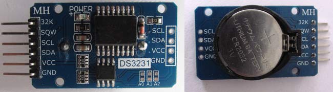
The DS3231 module communicates with the help of I2C protocol, so if you are not aware of what it is and how it is used with PIC read the I2C with PIC tutorial before proceeding. Also in this tutorial we are going to create a header file which can be used to communicate with our RTC module and also test the same on hardware by displaying the time and date on a LCD display so it is also important to learn how to interface LCD display with PIC microcontroller. The header file created in this tutorial for DS3231 can later be used/modified to suit your applications.
We have previously used DS3231 RTC with Arduino in below projects:
Connecting the DS3231 RTC with PIC Microcontroller:
Circuit diagram for PIC Microcontroller based Digital Clock is given below. As told earlier the DS3231 works with the help of I2C communication so it will have a Serial Clock (SCL) and a Serial Data (SDA) pin which has to be connected to the I2C pins on our PIC which is the pin 18(SCL) and pin 23 (SDA). A pull up resistor of value 4.7k is used to keep the bus at high state when idle.
An LCD display is also connected to the pins on Port D to display the current date and time. The complete circuit diagram was designed on proteus and is shown below. We are going to use the same to simulate or program later in this tutorial.
 with PIC micro-controller")
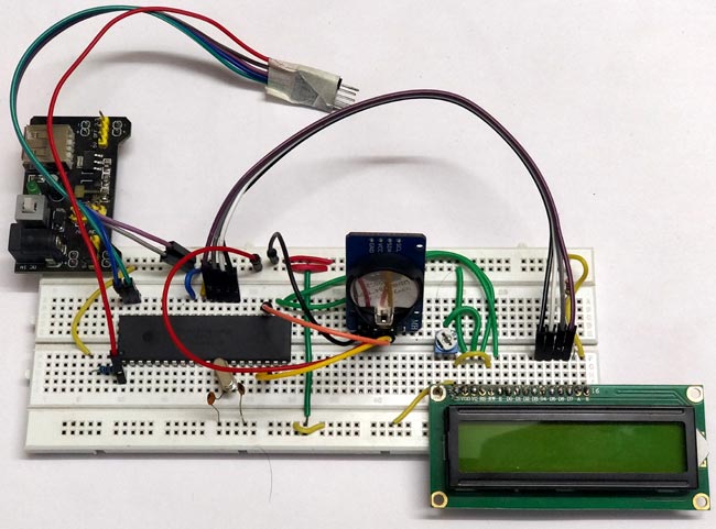
Follow the circuit diagram and make the connections accordingly, the I2C box shown above is used for I2C debugging so we will not include that in our connections. Also it is not shown that the RTC module has to be powered with a +5V supply using the Vcc and Ground pins on the module. I used my breadboard to make the connection and after making the required connections my set-up looked something like this below.
If you are new to PIC Microcontroller then start with Getting started with PIC Microcontroller.
Programming PIC for RTC Module:
The complete program for this Digital clock can be downloaded from the ZIP file here. The program includes three header files altogether. They are the lcd.h file for working with LCD display, the PIC16F877a_I2C.h file for working with I2C communication with PIC and finally the PIC16F877a_DS3231.h file to work with RTC modules. All the three header files are required for this program and are available in the ZIP file above. Further below I will explain the main program which uses all these header file to read the time and date from the RTC module and display it on the LCD screen. After that I will explain what actually is happening inside the RTC header file. As always begin the program by setting up the configuration bits and setting the clock frequency as 20MHz since that is what we have used in our hardware.
#pragma config FOSC = HS        // Oscillator Selection bits (HS oscillator)
#pragma config WDTE = OFF       // Watchdog Timer Enable bit (WDT disabled)
#pragma config PWRTE = ON       // Power-up Timer Enable bit (PWRT enabled)
#pragma config BOREN = ON       // Brown-out Reset Enable bit (BOR enabled)
#pragma config LVP = OFF        // Low-Voltage (Single-Supply) In-Circuit Serial Programming Enable bit (RB3 is digital I/O, HV on MCLR must be used for programming)
#pragma config CPD = OFF        // Data EEPROM Memory Code Protection bit (Data EEPROM code protection off)
#pragma config WRT = OFF        // Flash Program Memory Write Enable bits (Write protection off; all program memory may be written to by EECON control)
#pragma config CP = OFF         // Flash Program Memory Code Protection bit (Code protection off)

#define _XTAL_FREQ 20000000
The next step would be to define the LCD pins, if you look at the hardware you can notice that we have connected the pins of LCD to PORT D from RD2 to RD7, so we define the same as shown below.
#define RS RD2
#define EN RD3
#define D4 RD4
#define D5 RD5
#define D6 RD6
#define D7 RD7
By default when you purchased the RTC module the correct time and date will not be set in it, so we have to set it through our program. So we declare variable for each data and feed in the real world time and date as shown below. At the time of uploading the program my time and date was 10:55 am on 6-5-2018 so I have set the variables as below. You can set the correct time and date as per your actual application
    /*Set the current value of date and time below*/
    int sec = 00;
    int min = 55;
    int hour = 10;
    int date = 06;
    int month = 05;
    int year = 18;
    /*Time and Date Set*/
Next we add all the header files that we discussed about. If you have downloaded and opened the program from the ZIP file then it will not be a problem else make sure all the header files are added to your source file or your project directory.
#include <xc.h>
#include "lcd.h"
#include "PIC16F877a_I2C.h"
#include "PIC16F877a_DS3231.h"
Since we have used the PORT D as the output pins for interfacing the LCD we have to declare them as output pins in our program and initialize the LCD display as shown below
   TRISD = 0x00; //Make Port D pins as outptu for LCD interfacing
   Lcd_Start(); // Initialize LCD module
The RTC module communicates with the help of I2C protocol so we have to enable the I2C communication our PIC microcontroller. Most devices including our DS3231 modules have an I2C operating frequency of 100KHz so we start the I2C communication with a frequency of 100KHz as shown below
I2C_Initialize(100); //Initialize I2C Master with 100KHz clock
As soon as we have established an I2C communication with the RTC module the first thing we do is set the current time and date that we entered in our program. This can be done by calling the set_Time_Date function as shown below. Once the time and date is set the module will automatically keep track of it and increment them just like a digital clock.
Set_Time_Date(); //set time and date on the RTC module
To indicate that the program has started we will display a small intro message for which will stay on the screen for 2seconds. This message will display RTC with PIC –Circuit Digest on the screen. The program for the same is shown below
     Lcd_Clear();
     Lcd_Set_Cursor(1,1);
     Lcd_Print_String("  RTC with PIC");
     Lcd_Set_Cursor(2,1);
     Lcd_Print_String(" -Circuit Digest");
     __delay_ms(1500);
Inside our infinite while loop we should read the current time and date and then display the values in our LCD screen. To read the Time and Date from the RTC module the Update_Current_Time_Date function can be used as shown below. This function will read the value form the RTC module and update the variables sec, min, hour, date, month and year with the current values. Then we can use them for our purpose.
Update_Current_Date_Time(); //Read the current date and time from RTC module
The variables are of integer data type, we have to convert them to individual characters so that we can display them on the LCD screen. So we use the modulus operator to get the once digit and divide the variable by 10 to get the tens digit. The same is done for all the variables.
    //Split the into char to display on lcd
     char sec_0 = sec%10;
     char sec_1 = (sec/10);
     char min_0 = min%10;
     char min_1 = min/10;
     char hour_0 = hour%10;
     char hour_1 = hour/10;
     char date_0 = date%10;
     char date_1 = date/10;
     char month_0 = month%10;
     char month_1 = month/10;
     char year_0 = year%10;
     char year_1 = year/10;
All that is left to do is displaying the information that we acquired in the LCD screen. This can be easily done with the LCD functions that we have previously discussed on our LCD tutorial. So the code to display time is given below, the same method is used to display the date as well. A delay of 500 ms is given after displaying the data so that it acts as an update interval.
         Lcd_Clear();
        Lcd_Set_Cursor(1,1);
        Lcd_Print_String("TIME: ");
        Lcd_Print_Char(hour_1+'0');
        Lcd_Print_Char(hour_0+'0');
        Lcd_Print_Char(':');
        Lcd_Print_Char(min_1+'0');
        Lcd_Print_Char(min_0+'0');
        Lcd_Print_Char(':');
        Lcd_Print_Char(sec_1+'0');
        Lcd_Print_Char(sec_0+'0');
Brief explanation of PIC16F877a_DS3231.h header file:
Things explained so far is sufficient to use the DS3231 module with PIC for your own projects, but for the curious minds out there would like to know what actually happens inside the header file and the data is actually received from the RTC module by PIC, just read further.
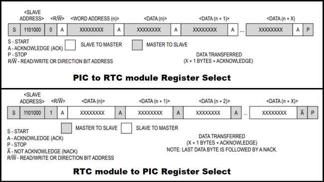
The best way to go through this, is by reading the datasheet of DS3231 completely. To give a brief of what is needed, the module acts as a slave to the PIC and the address of all DS3231 module is D0. So write data to the module we have to pass the address D0 and to Read data from RTC we have to pass the address D1. If we pass the write address the RTC module we get prepared to get data from PIC so the consequent data written by the PIC will be received and saved in the RTC module. Similarly if we send the address for Read then PIC should get ready to Read the values from RTC since the RTC module will start sending all the data it has. The bit sequence for both D0 and D1 is shown below from the datasheet. Notice the address 0b11010000 stands for D0 (Write) and 0b11010001 stands for D01(Read)
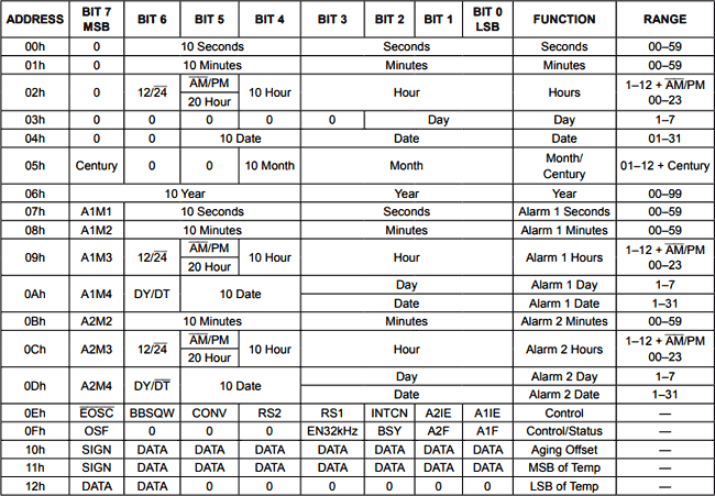
When the PIC sends the address D0 or D1 either to write or read, the following data should read or written in an order. This order is shown in the table below. So the first data will be sec (00h) followed by minutes (01h) followed by hours (02h) followed by day (03h) and upto MSB of Temperature.
The RTC module does not understand Decimal values, it communicates only through BCD values. So before writing any values to RTC module it should be converted to BCD and also the values received from the RTC module will be in BCD format and it should be convert to Decimal to make sense for us. With this in mind lets create all the function required for the using the RTC module.
BCD_2_DEC and DEC_2_BCD functions:
The first two functions would be used to convert the BCD data to Decimal and the Decimal data to BCD since the RTC module understands only BCD. The formulae to convert BCD to Decimal and for BCD to Decimal is
Decimal = (BCD >> 4) * 10 + (BCD & 0x0F)

BCD = ((Decimal / 10) << 4) + (Decimal % 10)
We just have to use these two formulas to create a function which takes in the opposite unit as parameter and converts it to required format and returns it, the function for doing the same is shown below
int  BCD_2_DEC(int to_convert)
{
   return (to_convert >> 4) * 10 + (to_convert & 0x0F);
}

int DEC_2_BCD (int to_convert)
{
   return ((to_convert / 10) << 4) + (to_convert % 10);
}
Set_Time_Date() function:
This function will write the value of time and date from the PIC to RTC module. The values of real time and date has to be updated in the variables sec, min, hour, date, month and year by the user. These values will then be converted into BCD and written to the RTC module.
As we discussed, to write a value to RTC module we have to pass the address D0 and write a bull bit 0 to initiate the writing process. Then we can send the data in the order as shown in the table above.
void Set_Time_Date()
{
   I2C_Begin();
   I2C_Write(0xD0);
   I2C_Write(0);
   I2C_Write(DEC_2_BCD(sec)); //update sec
   I2C_Write(DEC_2_BCD(min)); //update min
   I2C_Write(DEC_2_BCD(hour)); //update hour
   I2C_Write(1); //ignore updating day
   I2C_Write(DEC_2_BCD(date)); //update date
   I2C_Write(DEC_2_BCD(month)); //update month
   I2C_Write(DEC_2_BCD(year)); //update year
   I2C_End();
}
Update_Current_Date_Time() function:
The last function in the library is the one used to read the time and date from the RTC module and pass it on to the PIC microcontroller. This function is split into three segments, one to initiate the reading process the second to read the values and save it to the global variables like sec, min, hour, date, month and year. And the third is to acknowledge that the reading was successful.
Notice that for each action the I2C communication should be started and ended.
To read the values from RTC we have to send the address D0 followed by a 0. This will make the RTC module send all the values it has in the order shown in table above. We can just read them convert them to Decimal and save it to the variables in the same order.
Finally, after the reading is done the RTC module will send an acknowledgment bit which should also be read and acknowledged.
void Update_Current_Date_Time()
{
   //START to Read
   I2C_Begin();
   I2C_Write(0xD0);
   I2C_Write(0);
   I2C_End();

  //READ
   I2C_Begin();
   I2C_Write(0xD1);                              // Initialize data read
   sec = BCD_2_DEC(I2C_Read(1));
   min = BCD_2_DEC(I2C_Read(1));
   hour = BCD_2_DEC(I2C_Read(1));
   I2C_Read(1);
   date = BCD_2_DEC(I2C_Read(1));
   month = BCD_2_DEC(I2C_Read(1));
   year = BCD_2_DEC(I2C_Read(1));
   I2C_End();

  //END Reading
    I2C_Begin();
    I2C_Write(0xD1);                              // Initialize data read
    I2C_Read(1);
    I2C_End();
}

Simulation:
The project can be simulated using the Proteus simulation software. Make the connections as shown in the circuit diagram and load the hex file in to the PIC controller. When you simulate it you will find two pop-up boxes and the date and time displayed on the LCD as shown below.

The small one on the top shows the time and date that is current inside the RTC module and the second pop-up is the I2C debugger. It is an excellent tool to check what data is actually being passed in and out the I2C bug.
Display Time and Date on LCD:
Once your hardware is ready and the code is downloaded as ZIP file through the link given open the program using the MPLABX IDE. You have to launch the IDE first and use the open project option and browse to the contents inside the ZIP file and open the .X folder.
Simply check if the program is compiling and upload the code into your hardware by using the PicKit3. As soon as the program is uploaded you should see the introductory message and then the time and date should be displayed as shown below.
If there is nothing on the LCD check your connections and make sure the contrast level is set correctly by varying the potentiometer. That is it how you can show time and date to all your PIC microcontroller projects and can use this as Digital Clock. Hope you learnt something new and enjoyed learning this tutorial. If you have faced any problem post them on the comments below or on the forums for technical help.
Download the complete PIC program for this project with header files from here and further check our all the PIC Tutorials here.
Complete Project Code
/*
 * File:   RTC_with_PIC_main.c
 * Author: Aswinth
 * More info: www.circuitdigest.com ;
 * Created on 5 May, 2018, 6:42 PM
 */
#pragma config FOSC = HS        // Oscillator Selection bits (HS oscillator)
#pragma config WDTE = OFF       // Watchdog Timer Enable bit (WDT disabled)
#pragma config PWRTE = ON       // Power-up Timer Enable bit (PWRT enabled)
#pragma config BOREN = ON       // Brown-out Reset Enable bit (BOR enabled)
#pragma config LVP = OFF        // Low-Voltage (Single-Supply) In-Circuit Serial Programming Enable bit (RB3 is digital I/O, HV on MCLR must be used for programming)
#pragma config CPD = OFF        // Data EEPROM Memory Code Protection bit (Data EEPROM code protection off)
#pragma config WRT = OFF        // Flash Program Memory Write Enable bits (Write protection off; all program memory may be written to by EECON control)
#pragma config CP = OFF         // Flash Program Memory Code Protection bit (Code protection off)
#define _XTAL_FREQ 20000000 //We are running on 20MHz crystal
//Define the LCD pins
#define RS RD2
#define EN RD3
#define D4 RD4
#define D5 RD5
#define D6 RD6
#define D7 RD7
/*Set the current value of date and time below*/
int sec = 00;
int min = 55;
int hour = 10;
int date = 06;
int month = 05;
int year = 18;
/*Time and Date Set*/
#include <xc.h>
#include "lcd.h" //Header for using LCD module
#include "PIC16F877a_I2C.h" // Header for using I2C protocal
#include "PIC16F877a_DS3231.h" //Header for using DS3231 RTC module
int main()
{
    TRISD = 0x00; //Make Port D pins as outptu for LCD interfacing
    Lcd_Start(); // Initialize LCD module
    I2C_Initialize(100); //Initialize I2C Master with 100KHz clock
    Set_Time_Date(); //set time and date on the RTC module
     //Give an intro message on the LCD
     Lcd_Clear();
     Lcd_Set_Cursor(1,1);
     Lcd_Print_String("  RTC with PIC");
     Lcd_Set_Cursor(2,1);
     Lcd_Print_String(" -Circuit Digest");
     __delay_ms(1500); //display for 1.5sec
while(1)
  {
    Update_Current_Date_Time(); //Read the current date and time from RTC module
    //Split the into char to display on lcd
     char sec_0 = sec%10;
     char sec_1 = (sec/10);
     char min_0 = min%10;
     char min_1 = min/10;
     char hour_0 = hour%10;
     char hour_1 = hour/10;
     char date_0 = date%10;
     char date_1 = date/10;
     char month_0 = month%10;
     char month_1 = month/10;
     char year_0 = year%10;
     char year_1 = year/10;
       //Display the Time on the LCD screen
        Lcd_Clear();
        Lcd_Set_Cursor(1,1);
        Lcd_Print_String("TIME: ");
        Lcd_Print_Char(hour_1+'0');
        Lcd_Print_Char(hour_0+'0');
        Lcd_Print_Char(':');
        Lcd_Print_Char(min_1+'0');
        Lcd_Print_Char(min_0+'0');
        Lcd_Print_Char(':');
        Lcd_Print_Char(sec_1+'0');
        Lcd_Print_Char(sec_0+'0');
        //Display the Date on the LCD screen
        Lcd_Set_Cursor(2,1);
        Lcd_Print_String("DATE: ");
        Lcd_Print_Char(date_1+'0');
        Lcd_Print_Char(date_0+'0');
        Lcd_Print_Char(':');
        Lcd_Print_Char(month_1+'0');
        Lcd_Print_Char(month_0+'0');
        Lcd_Print_Char(':');
        Lcd_Print_Char(year_1+'0');
        Lcd_Print_Char(year_0+'0');
        __delay_ms(500); //refresh for every 0.5 sec
  }
    return 0;
}
Comments
Should be some hardware
Should be some hardware problem are you sure that the code got uploaded successful ?
not working in controller.
not working in controller. maybe error in code.
Does it compile? IF not paste
Does it compile? IF not paste your error here
You could add two momentary
You could add two momentary contact push button switches that will allow you to initialize the time and date. I have used that method on some of my PIC projects, including a module similar to this one. I program in assembly language but if you want to see my version go to:
boomerrules.com/i2c-real-time-clock
Sir can u please tell me how
Sir can u please tell me how to add temp in it
and in code what is page number
trouble switching to 16F1938
Hi - thanks so much for this project. The code is very clear and it was easy to test and understand!'
I am looking to deploy this code in a home project using a PIC16F1938. It was possible to get it running in Proteus with little trouble. However, when I load it to a live PIC, it hangs up when reading the time (when it reads the seconds, it comes back with a value of 0xD1 (what we put in the buffer to send a read command to the DS3231) and then when the I2C_Hold functin is called at the start of reading the minutes the SSPCON2 register has a value of 0x10 and it locks up.
I am convinced that I have made a wiring problem, but have confirmed the following:
- VDD - 5V
- SDA and SDC both have a pull-up via 10K resistors
- GND connected
Are there any gotchas for I2C that I may be missing???
i wanted to use interrupt to
i wanted to use interrupt to stay in the same loop can anyone figure me out.

It works perfect on Proteus using pic18f4550 but it does not work when I charge the hex to the pic. Apparently the pic does not communicate with the module